Cube & Tetrahedron: Worked Problems (Leaving Cert DCG): Revision Notes
Cube & Tetrahedron: Worked Problems
Understanding how to create sections of 3D solids like cubes and tetrahedra is essential for technical drawing. These worked problems demonstrate the step-by-step process of finding true shapes when solids are cut by planes at various angles.
The key to mastering these problems lies in understanding the relationship between different orthographic views and how auxiliary projections help reveal information that may be hidden or foreshortened in principal views.
When working with 3D solids, always remember that what appears distorted in one view may show its true characteristics in another. This is why multiple views and auxiliary projections are crucial for complete understanding.
Cube section problems
Finding a square section at 40° angle
When a cube is sectioned by a plane inclined at 40° to the horizontal, we need to find the true shape of the resulting section. The process involves several key steps that build upon orthographic projection principles.
First, we establish the basic orthographic views of the cube, showing both plan and elevation views. The cube must be positioned so that we can clearly see how the sectioning plane intersects with it.
Worked Example: Square Section Construction
Step 1: Set up orthographic views of the cube
- Draw plan view showing the cube from above
- Draw elevation view showing the cube from the front
Step 2: Apply the auxiliary view method
- Create auxiliary view perpendicular to one principal view
- Position viewing direction parallel to the sectioning plane
Step 3: Find the true shape
- Project all intersection points to the auxiliary view
- Connect the points to reveal the true square section
The auxiliary view method is crucial here. When we want to find the true length of any line that appears shortened in both plan and elevation views, we must create an auxiliary view. This auxiliary view is drawn perpendicular to one of the principal views, with the viewing direction parallel to the line we want to see in its true length.
For the square section problem, we rotate the base of the cube in the auxiliary plane to make an 80° angle with the x-y axis. This rotation helps us position the cube correctly for the sectioning process. We then complete the cube in auxiliary view by projecting all points perpendicular to the hinge line.
The hinge line acts as the connection between the main view and auxiliary view. Heights for the auxiliary view are found by projecting from the main elevation view, ensuring all proportions remain accurate.
Cube with 50mm side elevation
This problem focuses on creating proper elevations when specific dimensions are given. Starting with a cube of known dimensions, we must set up accurate orthographic projections.
The process begins by setting up the plan view with proper positioning on the horizontal plane. An auxiliary plane is then created parallel to one face, allowing us to project the cube accurately. The key is maintaining consistent measurements throughout all views.
When constructing auxiliary views for cubes, remember that parallel lines in 3D space remain parallel in any orthographic view. This principle helps maintain accuracy when transferring measurements between views.
Tetrahedron section problems
Base of tetrahedron on horizontal plane
Working with tetrahedra requires understanding how triangular faces appear in different views. When the base of a tetrahedron rests on the horizontal plane, specific projection techniques must be applied.
The plan view shows the triangular base in its true shape since it lies flat on the horizontal plane. However, the other faces of the tetrahedron will appear foreshortened in this view and require auxiliary projections to find their true shapes.
Setting up the plan involves ensuring that one edge rests completely on the horizontal plane, making that edge appear as a true length in plan view. The tetrahedron can then be constructed by projecting the apex to its correct position above the base.
Worked Example: Tetrahedron Base Construction
Step 1: Draw the triangular base in plan view
- Position one edge parallel to a reference line
- Ensure the triangle shows true shape and size
Step 2: Locate the apex position
- Project vertically from the centroid of the base triangle
- Set the apex at the correct height for the tetrahedron
Step 3: Complete all views
- Project all edges to elevation and auxiliary views as needed
- Verify that all triangular faces are properly represented
Tetrahedron with inscribed sphere
This advanced problem combines the principles of tetrahedron projection with the additional complexity of an inscribed sphere. The sphere touches all four faces of the tetrahedron at their centres.
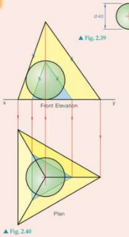
There is only one size of tetrahedron that will fit around a sphere of given radius, making this a highly constrained geometric problem. The tetrahedron must be positioned so that it can be drawn in multiple orthographic views while showing the sphere's relationship to each face.
Drawing the sphere in plan and elevation requires understanding that it appears as a circle in any orthographic view. The challenge lies in ensuring that the sphere truly touches all faces of the tetrahedron, which can only be verified through accurate geometric construction.
Key techniques and methods
Auxiliary view construction
Understanding auxiliary view construction is fundamental to solving complex 3D problems effectively.
Auxiliary views are essential when finding true lengths and true shapes of lines and surfaces that appear foreshortened in principal views. The auxiliary plane is always drawn perpendicular to one of the principal planes and parallel to the line or surface being investigated.
The hinge line represents the intersection between the principal plane and auxiliary plane. All measurements perpendicular to this hinge line are transferred from the adjacent principal view.
True shape determination
To find the true shape of any surface, we must view it in a direction perpendicular to that surface. This often requires creating auxiliary views where the surface appears edge-on in one view, then creating a second auxiliary view to see the true shape.
The process of finding true shapes typically involves two stages: first finding where the surface appears as an edge (edge view), then creating a view perpendicular to that edge to reveal the true shape.
Projection principles
Remember that orthographic projection maintains parallel projection lines between all views. Points that align in one view must align consistently in all related views. This principle ensures geometric accuracy throughout the drawing process.
Exam tips
Here are essential strategies for succeeding in technical drawing examinations involving 3D solids:
Key Strategies for Success:
- Always start with the view that shows the most information clearly
- Use construction lines lightly and keep them visible for marking
- Label all key points consistently across all views
- Check that corresponding points align properly between views
- Measure carefully and use appropriate drawing instruments
- Show your construction method clearly - marks are awarded for method as well as accuracy
Remember!
These fundamental principles will help you tackle any 3D solid sectioning problem with confidence:
Essential Points to Remember:
- Auxiliary views are needed whenever you want to find true lengths or true shapes that are foreshortened in principal views
- The hinge line is your key reference for transferring measurements between principal and auxiliary views
- Parallel lines in 3D space remain parallel in any orthographic projection
- True shapes can only be seen when viewing perpendicular to the surface
- Always maintain consistent alignment of points between all related views