Projection of Solids Cut by Oblique Planes (Leaving Cert DCG): Revision Notes
Projection of Solids Cut by Oblique Planes
Understanding oblique planes
An oblique plane is a cutting plane that is neither parallel nor perpendicular to the principal planes of projection. When a solid object is cut by an oblique plane, we need to show both the plan view (looking down from above) and the elevation view (looking from the side) of the resulting cut solid.
The key to solving these problems is understanding how the cutting plane intersects with the solid and how to project the true shape of the cut surface onto both views.
Cutting rectangular prisms
When cutting a rectangular prism with an oblique plane, you need to follow a systematic approach to ensure accuracy in both views.
The fundamental process involves:
- Identify where the cutting plane intersects the edges of the prism
- Mark these intersection points in both plan and elevation views
- Connect these points to show the cut surface
- Show the remaining solid after the cut has been made
The process involves using vertical planes that run parallel to one of the coordinate axes to help solve the problem. These vertical planes intersect the oblique cutting plane along straight lines, which makes the construction much easier to manage.
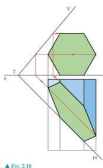
Working with hexagonal prisms
Hexagonal prisms present a more complex challenge because of their six-sided cross-section. The method remains similar but requires more intersection points to be found and projected.
When cutting a hexagonal prism, the systematic approach involves:
- Horizontal section planes are used to establish where the oblique plane intersects each level of the hexagon
- These section planes run parallel to the horizontal plane
- The intersection points are then projected between the plan and elevation views
- The true shape of the cut can be constructed by connecting all intersection points
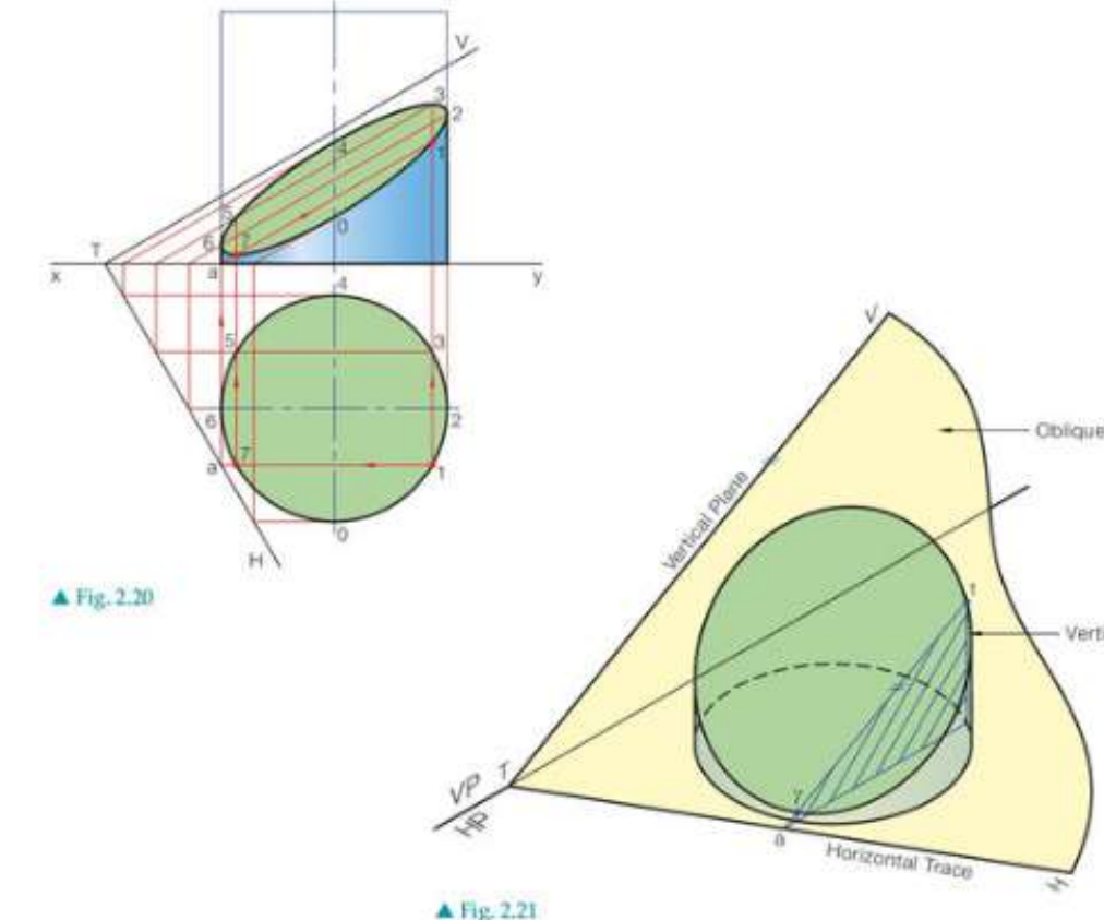
Projecting cut cylinders
Cylinders require a slightly different approach because of their curved surfaces. The cutting process involves working with the curved nature of the cylindrical form.
The systematic approach includes:
- Drawing vertical planes to cut the cylinder at specific points
- Finding where these vertical planes intersect the oblique cutting plane
- Projecting these intersection points to show the elliptical cut surface
- Using a series of vertical planes to get enough points for an accurate curve
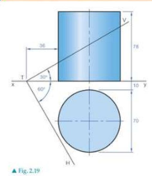
For cylindrical solids, the problem is often solved using a series of vertical planes. Each vertical plane cuts through the cylinder and intersects the oblique plane along a straight line. The points where these lines cross the surface of the cylinder can then be projected to create the cut surface.
Understanding cone sections
Cones present unique challenges when cut by planes. There are two main types of cutting to consider, each producing different geometric results.
Simply inclined planes
When a cone is cut by a simply inclined plane that passes through the apex, the resulting section will always be a triangle. This is because the cutting plane contains the apex point and intersects the cone along straight lines.
Oblique planes
When cutting a cone with an oblique plane that doesn't pass through the apex, the section can produce various conic sections depending on the angle and position of the cutting plane.
The possible resulting shapes include:
- Circles (if the plane is perpendicular to the axis)
- Ellipses (if the plane is at an angle to the axis)
- Parabolas (if the plane is parallel to a generator)
- Hyperbolas (if the plane cuts both nappes of the cone)
Construction techniques
The construction process follows a systematic methodology that ensures accurate representation in both views.
Step-by-Step Construction Process:
Step 1: Establish the cutting plane - Mark the oblique plane clearly in both views using its traces (lines where it intersects the coordinate planes)
Step 2: Use auxiliary planes - Employ vertical or horizontal section planes to break down the complex intersection into manageable parts
Step 3: Find intersection points - Locate where the auxiliary planes meet both the solid and the cutting plane
Step 4: Project between views - Transfer intersection points accurately between plan and elevation views
Step 5: Join the points - Connect intersection points to show the cut surface and the remaining solid
Essential tips for accuracy:
- Always work systematically, using the same auxiliary planes in both views
- Check that corresponding points align between plan and elevation
- Use enough section planes to ensure smooth curves where needed
- Remember that straight edges in the solid remain straight after cutting
Key Points to Remember:
- Oblique planes are neither parallel nor perpendicular to the principal planes of projection
- Simply inclined planes through a cone's apex always create triangular sections
- Use auxiliary planes (vertical or horizontal) to break complex intersections into manageable steps
- Always show both plan and elevation views of the cut solid
- Project intersection points accurately between views to ensure the cut surface is correctly represented