Development of Oblique Solids (Leaving Cert DCG): Revision Notes
Development of Oblique Solids
Understanding oblique solids
An oblique solid is a three-dimensional shape where the edges or sides are not perpendicular to the base. Unlike right solids (where all edges meet the base at 90°), oblique solids are "slanted" or "tilted", making their development more challenging.
The development (or net) of a solid is the flat pattern you get when you unfold all its surfaces onto a flat plane. This is essential for creating templates for manufacturing, packaging design, and construction work.
Understanding oblique solids is crucial for advanced technical drawing and manufacturing. These shapes appear frequently in real-world applications where structural considerations require angled supports or artistic designs demand non-perpendicular elements.
Key principles for developing oblique solids
When working with oblique solids, you must always work with true lengths. A true length is the actual measurement of an edge in 3D space, not the shortened version that appears in plan or elevation views due to perspective.
The standard approach involves three main views:
- Plan view - looking down from above
- Elevation view - looking from the side
- Development - the unfolded flat pattern
Critical Concept: Never use measurements directly from plan or elevation views for oblique solids. The foreshortening effect will make your development inaccurate and impossible to fold correctly. Always construct true lengths through geometric projection.
Development of oblique prisms
Oblique prisms have polygonal bases connected by parallelogram-shaped side faces. The development consists of the two parallel bases plus all the rectangular side faces arranged in a strip.
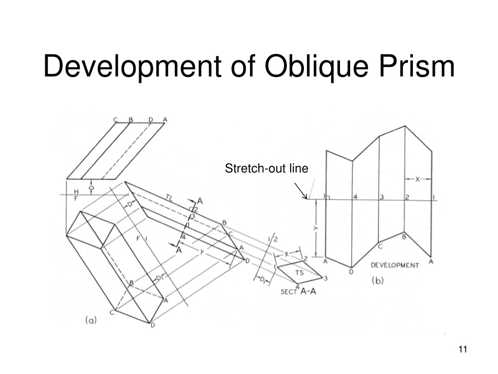
Worked Example: Developing an Oblique Pentagonal Prism
Step 1: Draw both the plan and elevation views to show the true shape and angle Step 2: Find the true lengths of all edges by using the elevation view Step 3: Choose a starting point and construct the base polygon Step 4: Add the side faces as rectangles using the true edge lengths Step 5: Complete by adding the second base at the end
The key challenge is that the side edges appear foreshortened in the plan view, so you must use geometric construction to find their actual lengths.
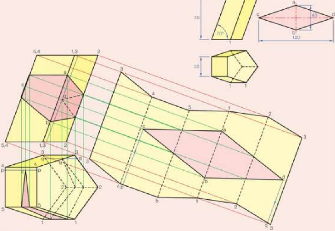
Development of oblique cylinders
Oblique cylinders have circular bases with curved surfaces that slant at an angle. The development creates a curved strip connecting two circles.
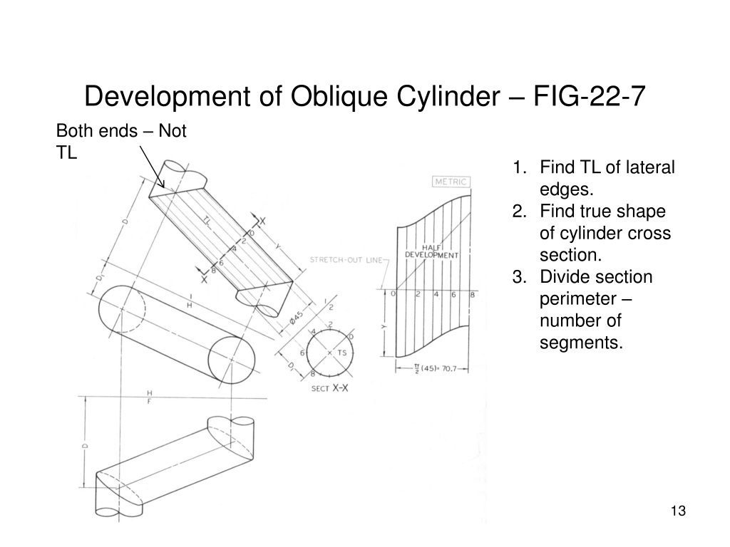
The construction process involves systematic division and projection to handle the curved surface accurately:
Worked Example: Developing an Oblique Cylinder
Step 1: Drawing plan and elevation views of the cylinder Step 2: Dividing the base circle into 12 equal parts (30° sectors) Step 3: Projecting these division points to the elevation view Step 4: Finding where each generator (surface line) intersects the top and bottom Step 5: Transferring these measurements to create the curved development Step 6: Adding the circular bases at each end
The resulting development shows how the curved surface "wraps around" to form the cylinder, with the characteristic curved edges showing the oblique angle.
Generators are the straight lines that run along the curved surface of cylinders and cones. In oblique cylinders, these lines are parallel to each other but not perpendicular to the base, creating the characteristic slanted appearance.
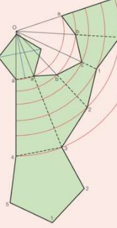
Development of oblique cones
Oblique cones have a circular base and a curved surface that tapers to an apex point, but the apex is not directly above the centre of the base.
The development method requires radial construction from the apex point:
Worked Example: Developing an Oblique Cone
Step 1: Dividing the base circle into equal radial segments Step 2: Finding the true length of each generator from base to apex Step 3: Starting the development with one generator as radius Step 4: Using compass arcs to mark off the true lengths sequentially Step 5: Creating a sector shape that represents the unfolded cone surface Step 6: Adding the circular base separately
For truncated oblique cones (cut cones), the process becomes more complex as you must account for two different boundary curves.
Truncated Oblique Cones: Follow similar steps but must also find the true lengths of generators to both the base and cut line, develop the surface between these two curves, and add both the base circle and the elliptical cut section.
Development of oblique pyramids
Oblique pyramids have polygonal bases with triangular faces meeting at an apex that is not centred above the base. Each face must be developed as an individual triangle with precise true-length measurements.
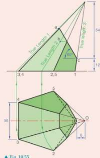
Worked Example: Square-Based Oblique Pyramid
Step 1: Finding the true length of every edge from base vertices to apex Step 2: Constructing each triangular face using these true lengths Step 3: Arranging the triangular faces around the base polygon Step 4: Ensuring all adjacent edges match exactly
For more complex pyramids like pentagonal-based ones, you must calculate true lengths for all five edges from base to apex, construct five triangular faces with accurate measurements, and arrange them systematically around the pentagonal base.
Advanced techniques for oblique pyramids include using auxiliary views to find true lengths and employing radial construction methods for better accuracy.
Common Mistake: Students often try to use the same edge length for all triangular faces in oblique pyramids. Remember that because the apex is not centred, each edge from base to apex will have a different true length that must be calculated individually.
Development of complex oblique prisms
More complex prisms like hexagonal oblique prisms follow similar principles but require careful attention to the increased number of faces and precise edge calculations.
For a hexagonal oblique prism, the development includes two hexagonal bases plus six rectangular side faces. Each rectangular face must be drawn using true edge lengths, and the arrangement requires precise measurement to ensure proper folding.
Construction Strategy: Use construction lines throughout the development process to maintain accuracy. Mark all measurement points clearly and double-check that adjacent edges match before finalising your development.
Essential construction techniques
Understanding these fundamental techniques is crucial for success with oblique solid developments:
Finding true lengths: Use geometric projection between plan and elevation views. The true length appears where you can see both the horizontal and vertical components of an edge.
Radial construction: For cones and curved surfaces, use the apex or centre as a focal point and swing arcs to transfer measurements.
Parallel projection: For cylinders and prisms, use parallel lines to transfer points between views accurately.
Sequential construction: Build developments step-by-step, checking measurements at each stage to avoid cumulative errors.
Pro Tip: Always work with sharp, well-maintained drawing instruments. Accuracy in oblique solid development depends on precise measurements and clean construction lines. Small errors compound quickly and will prevent successful folding.
Exam tips
Examination Success Strategies
- Always start with clear plan and elevation views
- Mark all true lengths before beginning the development
- Use construction lines to maintain accuracy
- Check that adjacent edges in your development match exactly
- Label key points consistently across all views
- Practice with different oblique angles to build confidence
Key Points to Remember:
- Oblique solids have edges or surfaces that are not perpendicular to their bases, making them more challenging to develop than right solids
- True lengths must always be found through geometric construction - never use the foreshortened lengths from plan or elevation views
- Each solid type requires a specific approach: prisms need rectangular faces, cones use radial construction, and pyramids require triangular faces
- Accuracy is crucial - small errors in measurements will prevent the development from folding correctly into the 3D shape
- Follow the construction sequence: plan view → elevation view → find true lengths → construct development