Developments (Leaving Cert DCG): Revision Notes
Developments
What is a development?
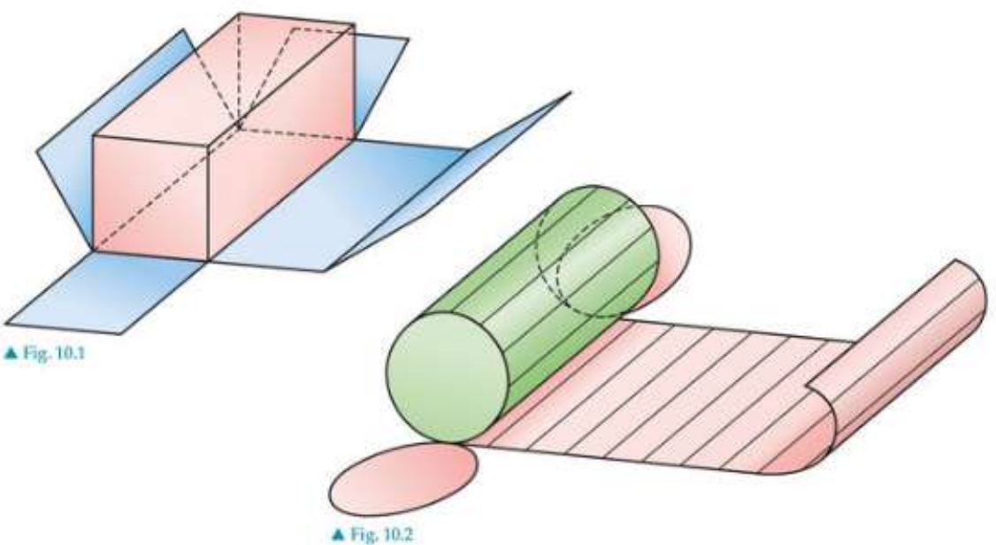
A development is the method of unfolding a 3D object's surface onto a flat plane. Think of it like unfolding a cardboard box - you're taking all the faces of a three-dimensional shape and laying them out flat in one piece. The fold lines between faces are shown as dashed lines in technical drawings.
Practical Applications in Industry
This technique is incredibly practical and widely used in manufacturing. When you see packaging for products, clothing patterns, or sheet metal components, these all started as developments. The packaging industry relies heavily on developments to create boxes and cartons from single sheets of cardboard, while sheet metal workers use them to cut and fold complex shapes.
Key principle of developments
Fundamental Rule of Developments
The most important rule to remember is: In a development, all lines are true lengths and all surfaces are true shapes. This means when you unfold a 3D shape, every measurement you draw must be accurate to the real object. You cannot simply copy measurements from plan or elevation views, as these often show shortened or foreshortened dimensions.
Types of developments
Rectangular prisms
The simplest development involves rectangular prisms (box shapes). The process involves systematically unfolding each face - front, back, left side, right side, top, and bottom - ensuring they connect properly along their edges.
Construction Method for Rectangular Prisms
The construction method involves:
- Drawing the front face first
- Adding the sides by taking true widths from the plan view
- Adding the top and bottom using true heights from the elevation view
- Ensuring all faces connect along fold lines
Pentagonal and hexagonal prisms
More complex prisms follow similar principles but require careful measurement of each face. For a pentagonal prism, you need to unfold five rectangular sides plus the pentagonal top and bottom.
Key Steps for Complex Prisms
- Taking true lengths from the elevation view for height measurements
- Taking true widths from the plan view for each face width
- Arranging the faces in a logical unfolding pattern
- Adding the pentagonal or hexagonal ends
Truncated prisms
When a prism is cut at an angle (truncated), the development becomes more complex because the cut creates irregular shaped faces. The true lengths of these cut edges must be found using geometric construction methods.
Handling Truncated Shapes
For truncated shapes:
- Project lines from the elevation to find true heights at cut points
- Use the plan view to determine the correct widths
- Calculate the true shape of the cut surface separately
- Join all elements ensuring proper alignment
Cylinders
Cylinders unfold into rectangles for the curved surface, plus two circles for the ends. The width of the rectangle equals the circumference of the cylinder, while the height equals the cylinder's height.
Worked Example: Cylinder Development
The construction involves:
Step 1: Divide the circular plan into equal parts (usually 12)
Step 2: Draw vertical generator lines in the elevation
Step 3: Create a rectangle with width = circumference and height = true height
Step 4: Add the circular ends
Pyramids
Pyramid developments create triangular faces that meet at a common apex. The key challenge is finding the true lengths of the pyramid edges, which requires arc construction methods.
Pyramid Construction Process
- Find the true length of each slant edge using geometric construction
- Draw each triangular face using these true lengths
- Arrange the triangular faces around a common vertex
- Use arc construction to ensure accurate edge lengths
Cones
Cone developments unfold into sectors (part of a circle). The radius of this sector equals the slant height of the cone, while the arc length equals the circumference of the cone's base.
Worked Example: Cone Construction
Step 1: Find the true slant height from elevation view
Step 2: Calculate the sector angle based on base circumference
Step 3: Draw the sector using the slant height as radius
Step 4: Add the circular base separately
Complex shapes with holes
Real-world applications often involve more complex developments, such as prisms with holes or multiple openings. These require careful planning to ensure all surfaces are accounted for in the development.
Approach for Complex Shapes
- Developing the main shape first
- Adding cut-out patterns for holes in their correct positions
- Ensuring hole positions align with the folded 3D form
- Marking fold lines clearly to avoid confusion
Construction techniques
Finding true lengths
Many development problems require finding the true length of lines that appear foreshortened in plan or elevation views. This typically involves creating auxiliary views, using arc construction methods, and applying geometric principles to reveal actual measurements.
Arc construction method
Worked Example: Arc Construction for Pyramids and Cones
Step 1: Use the apex as centre point
Step 2: Set compass to true edge length
Step 3: Step around to mark each face position
Step 4: Connect points to create the development
Generator method
For cylinders and cones, divide the circular plan into equal parts and project these division points through the construction. This ensures accurate surface development.
Practical applications
Industries Using Developments
Developments are essential in many industries:
- Packaging: Creating boxes, cartons, and containers from flat sheets
- Sheet metal work: Manufacturing ducts, pipes, and complex metal forms
- Clothing industry: Creating patterns for cutting fabric
- Architecture: Planning folded roof structures and cladding systems
Remember!
Key Points to Remember:
- All lines in developments must be true lengths - never copy directly from plan or elevation views without checking
- All surfaces must be true shapes - faces may appear distorted in orthographic views but must be accurate in the development
- Use geometric construction methods to find true lengths of slant edges and cut surfaces
- Plan your layout carefully before starting to ensure all faces fit together logically
- Mark fold lines with dashed lines to distinguish them from cut edges (solid lines)