Downcut Milling (Climb Milling) (Leaving Cert Engineering): Revision Notes
Downcut Milling (Climb Milling)
What is downcut milling?
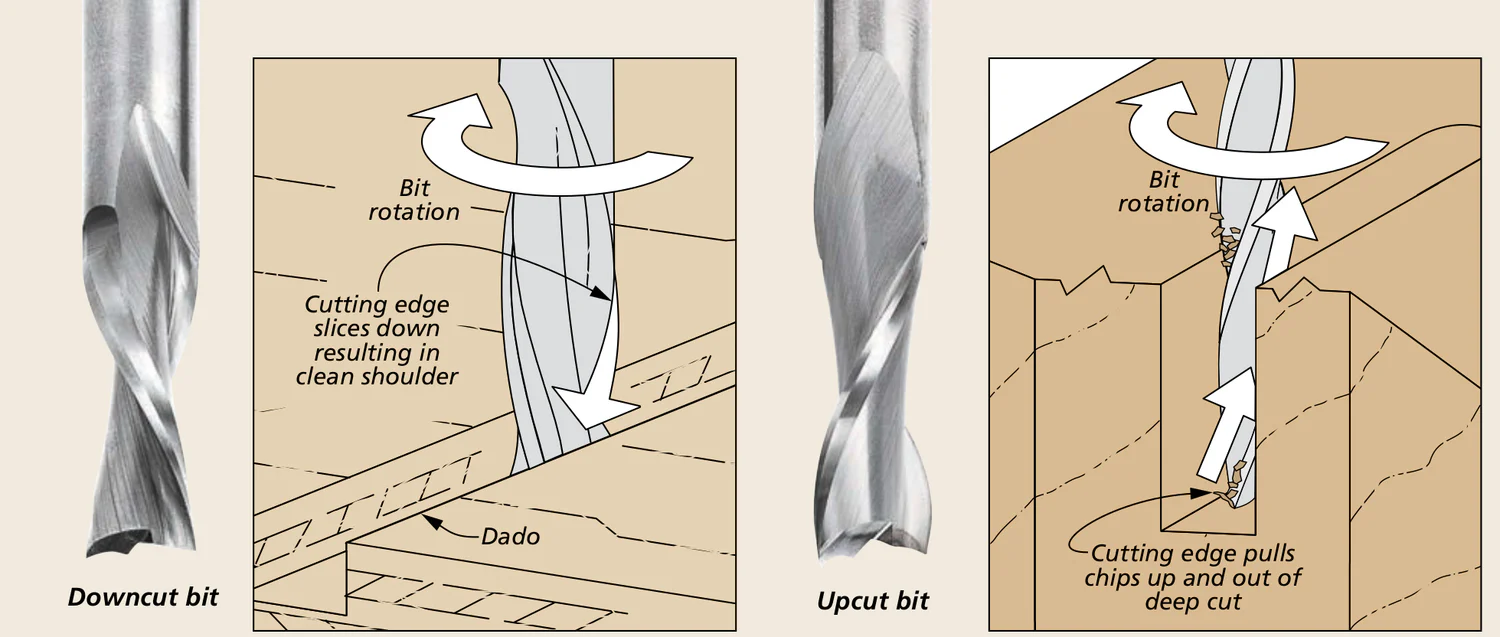
Downcut milling, also known as climb milling, is a machining process where the cutting tool rotates in the same direction as the workpiece feed. This means the cutter moves along with the work during the cutting operation, which differs from conventional milling methods.
The key characteristic of this process is that the cutting tool and workpiece move together, creating a specific cutting action that has both advantages and disadvantages compared to standard milling techniques.
Process characteristics
In downcut milling, the cutting action produces chips that start large and then reduce in size as the cut progresses. This variation in chip size creates an uneven cutting force that leads to increased machine vibration. The vibration occurs because the cutting action is not smooth - the constantly changing chip size means the cutting forces are not consistent throughout the operation.
The cutting tool enters the material with maximum engagement and gradually reduces contact as it completes the cut. This creates the characteristic chip formation pattern that gives downcut milling its unique properties.
The varying chip formation is what distinguishes downcut milling from conventional milling methods. Understanding this chip formation pattern is essential for predicting the machining behaviour and selecting appropriate cutting parameters.
Advantages of downcut milling
The primary benefit of downcut milling is that it requires less clamping force to secure the workpiece. This happens because the cutting tool naturally pushes the work into the machine table and holding fixtures. The downward and inward cutting forces help to hold the workpiece in position, reducing the need for extensive clamping arrangements.
This reduced clamping requirement can be particularly useful when machining delicate or thin workpieces that might be damaged by excessive clamping pressure.
The self-clamping action of downcut milling makes it especially valuable for machining thin-walled components or fragile materials where traditional clamping methods might cause deformation or damage.
Disadvantages of downcut milling
The main drawback is the increased vibration caused by the varying chip formation. This vibration can affect:
- Surface finish quality
- Tool life
- Machine accuracy
- Overall machining stability
Due to these vibration issues, downcut milling is not the standard machining method for most applications.
The vibration problems in downcut milling can be significant enough to compromise the quality of the finished product. This is why conventional milling is typically the preferred method unless the specific advantages of downcut milling are required for the application.
Work holding methods
Dividing head
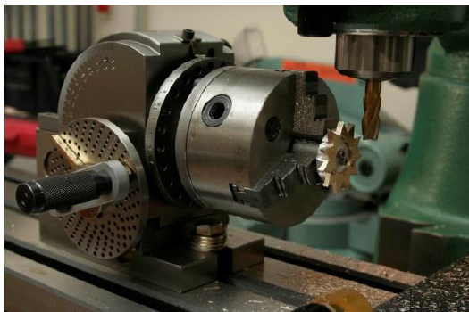
A dividing head is a specialised work holding device designed for positioning cylindrical materials on the milling machine table. This device contains an internal worm and wheel mechanism that allows the operator to rotate the workpiece through precise, controlled angles.
The dividing head is particularly useful for:
- Machining flat surfaces on cylindrical bars
- Creating gear teeth on blank material discs
- Performing indexing operations requiring precise angular positioning
When the dividing head is positioned horizontally, it may also be called a turntable. This versatility makes it an essential work holding tool for complex milling operations requiring precise workpiece positioning.
Practical Application: Gear Cutting
Step 1: Mount the gear blank on the dividing head Step 2: Calculate the indexing required Step 3: Cut the first tooth using the milling cutter Step 4: Index the workpiece to the next position Step 5: Repeat until all teeth are cut
Related finishing processes
Precision grinding
Precision grinding serves as a finishing process that complements milling operations. While milling removes large amounts of material quickly, precision grinding removes only tiny amounts of material to achieve extremely smooth and accurate surface finishes.
The grinding process uses a grinding wheel made from abrasive materials bonded together, similar to sandpaper but much more robust. These wheels rotate at high speeds, typically between 2000-5000 RPM.
During grinding, the workpiece is secured to a machine table and moved against the rotating grinding wheel using reciprocating table motion. This back-and-forth movement allows the work to pass under the grinding wheel multiple times, gradually achieving the desired finish and dimensional accuracy.
The high rotational speeds in precision grinding generate significant heat, which is why coolant systems are essential for preventing thermal damage to the workpiece and maintaining dimensional accuracy.
Key Points to Remember:
- Downcut milling involves the cutting tool moving with the workpiece feed direction
- The process creates varying chip sizes that cause increased machine vibration
- Less clamping force is required because the cutting action pushes work into the fixtures
- Dividing heads enable precise angular positioning of cylindrical workpieces
- Precision grinding provides the final smooth finish after milling operations