Gears (Leaving Cert Engineering): Revision Notes
Gears
What are gears?
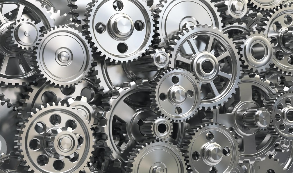
Gears are rotating mechanical components with teeth that mesh together to transmit power and motion between machine parts. They are essential components found in countless mechanical devices, from simple hand tools to complex machinery.
The primary purpose of gears is to provide gear reduction in motorised equipment. This is crucial because small motors often spin very fast but produce limited torque. Gears solve this problem by trading speed for increased turning force.
The fundamental principle of gears is the speed-torque trade-off: as rotational speed decreases through gear reduction, the available torque (turning force) increases proportionally. This makes gears invaluable for applications requiring high torque at lower speeds.
Applications of gears
Gears serve several important functions in mechanical systems:
- Speed reduction and torque increase - The most common application
- Direction change - Gears can redirect rotational motion by 90 degrees or other angles
- Power transmission - Moving energy from one part of a machine to another
Practical examples
Worked Example: Electric Screwdriver
An electric screwdriver demonstrates gear reduction perfectly. The motor produces high speed but low torque, whilst the screwdriver needs lots of turning force to drive screws. A large gear reduction system converts the motor's fast, weak rotation into slow, powerful rotation.
Process:
- Motor spins at high RPM with low torque
- Gear system reduces speed significantly
- Output delivers high torque at low RPM
- Result: Effective screw driving capability
Worked Example: Car Differential
Car differentials show how gears change direction. Power travels down a central shaft, and the differential uses gears to turn that power 90 degrees to drive the wheels.
Process:
- Engine power transmitted via driveshaft
- Ring and pinion gears redirect power 90°
- Differential gears distribute power to wheels
- Result: Wheels receive rotational power
Gear ratio
Gear ratio is the mathematical relationship between the number of teeth on two meshing gears or two sprockets connected by a common chain.
The gear ratio determines how speed and torque change between the input and output. When gears have different sizes:
- The larger gear rotates more slowly but with greater torque
- The smaller gear rotates faster but with less torque
Understanding gear ratios is essential for mechanical design. A higher gear ratio (like 4:1) provides more torque multiplication but greater speed reduction. Always consider both the speed and torque requirements of your application when selecting gear ratios.
Types of gears - spur gears
Spur gears (also called straight-cut gears) are the most basic type of gear system. They represent the simplest form of power transmission and are widely used in mechanical applications.
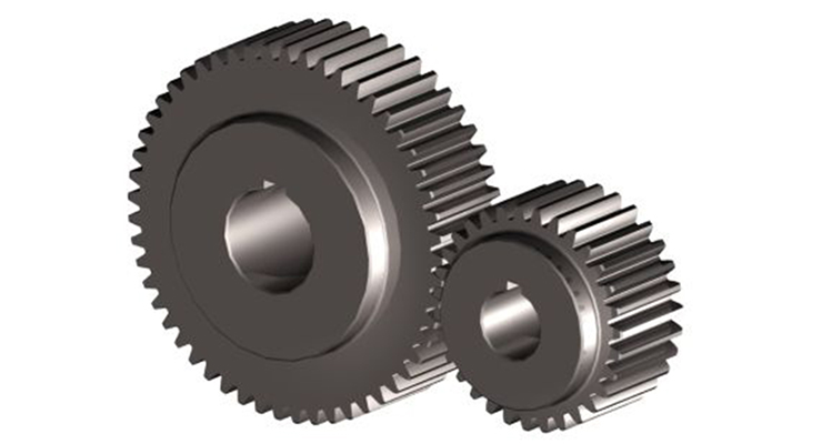
They have several distinctive characteristics:
- Consist of a cylindrical disc with teeth projecting outward
- Teeth are straight and run parallel to the axis of rotation
- Must be mounted on parallel shafts to mesh properly
- Provide the simplest form of power transmission between parallel axes
Spur gears are widely used because of their simplicity, efficiency, and ease of manufacture. They work well for applications requiring moderate speeds and loads.
While spur gears are the most straightforward gear type, they do have limitations. At high speeds, they can be noisy due to the sudden engagement of teeth. For quieter operation or higher speeds, helical gears might be preferred despite their increased complexity.
Key Points to Remember:
- Gears trade speed for torque - slower output means stronger turning force
- Gear ratio compares the number of teeth between meshing gears
- Spur gears are the simplest type with straight teeth on parallel shafts
- Gear reduction is essential for converting high-speed, low-torque motor output into useful mechanical power
- Direction changes are possible using gear systems, such as in car differentials