Current in a Magnetic Field (Leaving Cert Physics): Revision Notes
Further Examples of Forces
When we study electromagnetism, we encounter several fascinating phenomena where electric currents and magnetic fields interact to produce forces. These forces form the foundation for many technological applications, from electric motors to particle accelerators.
The motor effect is the fundamental principle underlying all these force interactions. It states that a current-carrying conductor placed in a magnetic field will experience a force, and this force can be used to create motion and perform useful work.
Force on a current-carrying coil in a magnetic field
When a rectangular coil carrying electric current is placed in a magnetic field, it experiences forces that cause it to rotate. This phenomenon is known as the motor effect and forms the basis for electric motors.
Consider a rectangular coil positioned perpendicular to a uniform magnetic field. The sides of the coil that are parallel to the magnetic field lines experience no force, whilst the sides that cut across the field lines experience forces according to Fleming's left-hand rule. These forces act in opposite directions on opposite sides of the coil, creating a turning moment or torque that causes the coil to rotate.
The magnitude of the force on each side of the coil is given by:
where:
- B is the magnetic flux density (measured in tesla, T)
- I is the current flowing through the conductor (measured in amperes, A)
- l is the length of the conductor in the magnetic field (measured in metres, m)
Practical Demonstration: Coil Rotation
When you place a current-carrying rectangular coil between the poles of a horseshoe magnet:
Step 1: Current flows through the coil Step 2: The vertical sides of the coil cut through the magnetic field lines Step 3: Forces act on opposite sides in opposite directions Step 4: This creates a turning moment that rotates the coil
As the coil rotates, the turning effect changes. When the coil reaches a vertical position, the forces no longer create a turning moment, and the coil would stop rotating if not for additional mechanisms.
Simple DC motor operation
A practical direct current (DC) motor uses a split-ring commutator and carbon brushes to ensure continuous rotation of the coil. This ingenious design overcomes the problem of the coil stopping when it reaches the vertical position.
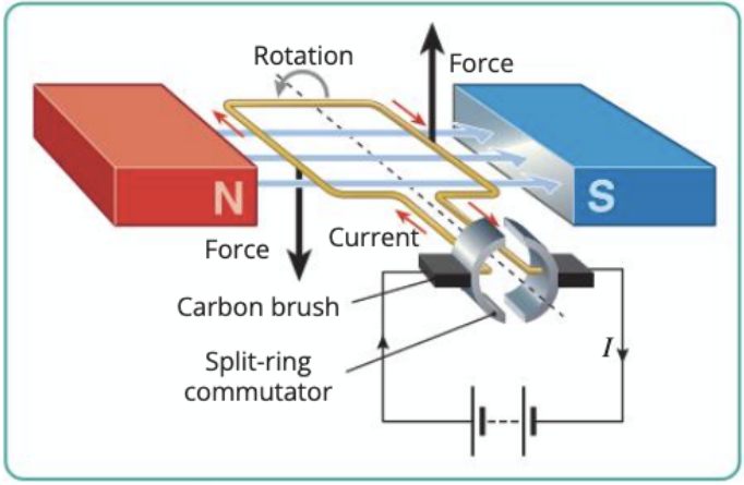
The key components of a simple DC motor include:
- Magnetic field: Created by permanent magnets (north and south poles)
- Rotating coil: The armature that carries the current
- Split-ring commutator: A segmented ring that reverses the current direction
- Carbon brushes: Make electrical contact with the rotating commutator
The split-ring commutator is absolutely essential for continuous motor operation. Without it, the coil would simply oscillate back and forth rather than rotate continuously. The commutator automatically reverses the current direction every half-turn, ensuring the forces always act in the same rotational direction.
The operation works as follows:
- Current flows through the coil via the carbon brushes and commutator
- The magnetic field exerts forces on the current-carrying sides of the coil
- These forces create a torque, causing the coil to rotate
- When the coil reaches the vertical position, the split-ring commutator reverses the current direction
- This ensures the forces continue to act in the same rotational direction
- The process repeats, maintaining continuous rotation
Force on a moving charge in a magnetic field
Individual charged particles moving through a magnetic field also experience forces. This is called the Lorentz force and explains phenomena such as the deflexion of electron beams in cathode ray tubes.
When a charged particle with charge q moves with velocity v through a magnetic field of flux density B, it experiences a force given by:
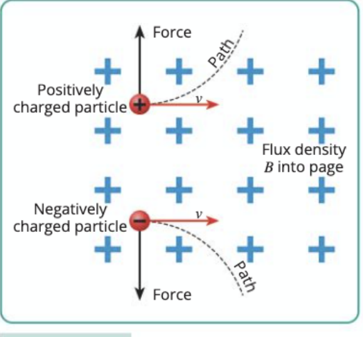
The direction of this force follows specific rules:
- For positive charges: Use Fleming's left-hand rule (conventional current direction)
- For negative charges: The force acts in the opposite direction
Key Applications of the Lorentz Force
The magnetic force on moving charges is used in many practical devices:
- Cathode ray tubes (deflecting electron beams to create images)
- Mass spectrometers (separating particles by mass-to-charge ratio)
- Particle accelerators (controlling and focusing particle beams)
Key characteristics of the magnetic force on moving charges:
- The force is always perpendicular to both the velocity and the magnetic field
- The force is maximum when the particle moves perpendicular to the field
- No force acts on charges moving parallel to the magnetic field lines
- The force changes the particle's direction but not its speed (since it acts perpendicular to motion)
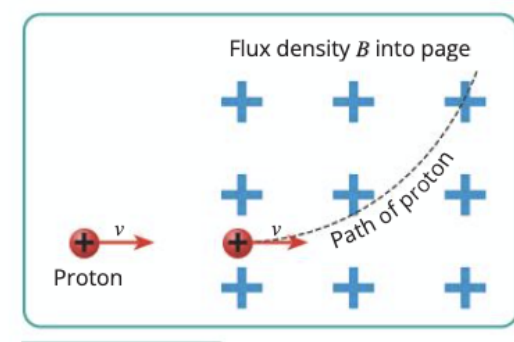
Charged particles moving in circular paths
When charged particles enter a uniform magnetic field at right angles, they follow circular or helical paths. This occurs because the magnetic force provides the centripetal force needed for circular motion.
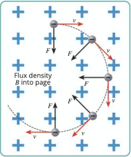
For a particle moving in a circle, the centripetal force equals the magnetic force:
Simplifying this equation gives the radius of the circular path:
where:
- m is the mass of the particle (kg)
- v is the particle's speed (m/s)
- r is the radius of the circular path (m)
- B is the magnetic flux density (T)
- q is the particle's charge (C)
Worked Example: Calculating Circular Path Radius
An electron (mass = 9.11 × 10⁻³¹ kg, charge = 1.60 × 10⁻¹⁹ C) moves at 2.0 × 10⁶ m/s perpendicular to a magnetic field of 0.50 T.
Step 1: Identify the given values
- m = 9.11 × 10⁻³¹ kg
- v = 2.0 × 10⁶ m/s
- B = 0.50 T
- q = 1.60 × 10⁻¹⁹ C
Step 2: Apply the formula r = mv/Bq r = (9.11 × 10⁻³¹ × 2.0 × 10⁶)/(0.50 × 1.60 × 10⁻¹⁹)
Step 3: Calculate the result r = 2.3 × 10⁻² m = 2.3 cm
Important observations about circular motion in magnetic fields:
- Heavier particles follow larger circular paths (larger radius)
- Faster-moving particles follow larger circular paths
- Stronger magnetic fields cause tighter circular paths (smaller radius)
- Particles with greater charge follow tighter circular paths
This principle is fundamental to the operation of devices such as cyclotron accelerators, mass spectrometers, and magnetic focusing systems.
Magnetic force between current-carrying conductors
Two parallel wires carrying electric current exert magnetic forces on each other. This interaction demonstrates that magnetic fields exist around any current-carrying conductor and that these fields interact with other currents.
Critical Rule for Current Direction
The direction of the currents determines whether the wires attract or repel:
- Parallel currents (same direction): Wires attract each other
- Anti-parallel currents (opposite directions): Wires repel each other
Remember this rule - it's essential for understanding electromagnetic interactions!
The behaviour depends on the direction of the currents:
Parallel currents (same direction):
- The wires experience an attractive force
- Each wire sits in the magnetic field created by the other
- The magnetic fields between the wires are in opposite directions, creating a weakened field region
- The stronger field regions on the outside push the wires together
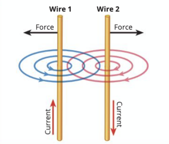
Anti-parallel currents (opposite directions):
- The wires experience a repulsive force
- The magnetic fields between the wires are in the same direction, creating a strengthened field region
- This stronger field region pushes the wires apart
The force per unit length between two parallel conductors is given by:
where:
- μ₀ is the permeability of free space
- I₁ and I₂ are the currents in the two conductors
- d is the distance between the conductors
Practical Applications
This principle has important real-world applications:
- Electromagnetic rail guns use conductor forces to accelerate projectiles
- Magnetic levitation (maglev trains) use repulsive forces for frictionless transport
- Power transmission lines must account for forces between cables during high current situations
Experimental demonstrations often use thin aluminium foil strips that visibly move when current flows, clearly showing the attractive or repulsive forces between current-carrying conductors.
Key Points to Remember:
-
Motor effect: Current-carrying conductors in magnetic fields experience forces that can cause rotation, leading to electric motor operation
-
Fleming's left-hand rule: Determines force direction on current-carrying conductors (First finger = Field, Middle finger = Current, Thumb = Motion)
-
Lorentz force: Moving charged particles in magnetic fields experience perpendicular forces (F = Bqv), causing deflexion without changing particle speed
-
Circular motion: Charged particles entering magnetic fields perpendicularly follow circular paths with radius r = mv/Bq
-
Conductor interactions: Parallel currents attract each other, whilst opposite currents repel, demonstrating the magnetic fields around current-carrying wires