Force Diagrams (Grade 11 NSC Matric Physical Sciences): Revision Notes
Force Diagrams
What are force diagrams?
Force diagrams are visual representations that help us understand the physical forces acting on objects. These sketches show the exact situation you're dealing with, using arrows to represent all forces acting on a system.
When you draw a force diagram, each arrow represents a specific force. The direction of the arrow shows which way the force acts, and the length of the arrow indicates the strength (magnitude) of that force.
Consider a simple example where a block rests on a horizontal surface. Two main forces act on this block:
- Gravitational force (Fg) pulls the block downward
- Normal force (N) pushes the block upward from the surface
In this situation, both forces have equal magnitude, which keeps the block in equilibrium.
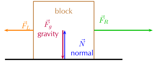
The diagram above shows a more complex situation where additional horizontal forces act on the block alongside the vertical forces. Notice how each force is clearly represented by an arrow that touches the object.
Essential guidelines for drawing force diagrams
Creating accurate force diagrams requires following specific rules that ensure your analysis remains correct:
Critical Rules for Force Diagrams:
Size and clarity requirements:
- Make your drawings large and clear - small, cramped diagrams lead to errors
- Draw neat lines using a ruler - precision matters in physics
- Ensure arrows touch the system or object - forces must clearly connect to what they're acting on
Arrow conventions:
- Use arrows to show force direction - the arrow's direction indicates exactly where the force points
- Arrow length represents force magnitude - longer arrows mean stronger forces, shorter arrows mean weaker forces
- Equal-length arrows indicate equal forces - this visual method helps you quickly identify balanced situations
Labelling requirements:
- All arrows must have clear labels - use standard notation like Fg for gravity, N for normal force
- Include a key if space is limited - this ensures clarity without cluttering your diagram
- Labels should specify both the force type and direction - for example, "normal force upward"
Additional details:
- Add known force values to your diagram - if you know specific measurements, include them
- Use consistent notation throughout - stick to the same symbols and abbreviations
Free body diagrams
Free body diagrams represent a simplified version of force analysis where we focus purely on the forces acting on an object. In these diagrams, you draw the object of interest as a simple dot, then show all forces as arrows pointing away from this dot.
This approach removes visual distractions and helps you concentrate on the force relationships. You can convert any regular force diagram into a free body diagram by replacing the detailed object drawing with a simple point.
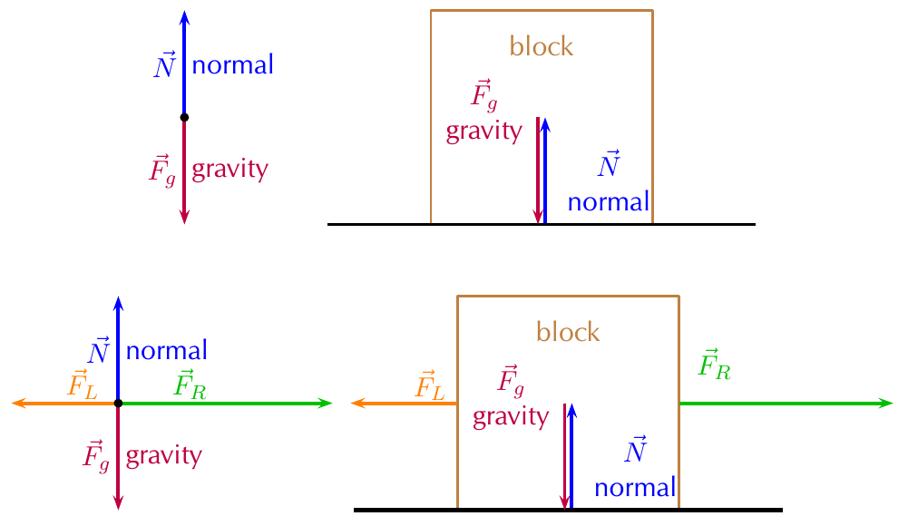
The diagram above demonstrates both approaches - the original force diagram showing the block on a surface, and the equivalent free body diagram showing the same forces acting on a central point.
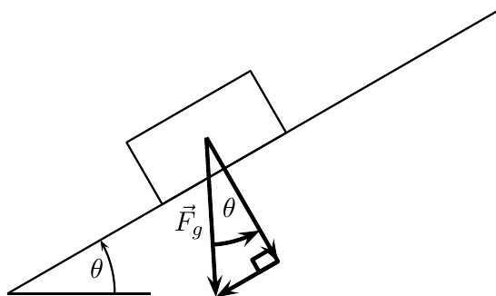
Resolving forces into components
When objects sit on inclined planes, force analysis becomes more complex because gravity no longer acts parallel or perpendicular to the surface. In these situations, you must break the gravitational force into components that align with your chosen coordinate system.
Setting up the coordinate system
The most effective approach involves aligning your coordinate system with the inclined plane itself. This means:
- The x-axis runs parallel to the inclined surface
- The y-axis runs perpendicular to the inclined surface
This alignment simplifies your calculations because other forces (like normal force and friction) naturally align with these axes.
Calculating force components
When gravity acts on an object on an inclined plane, you can split this force into two components using trigonometry:
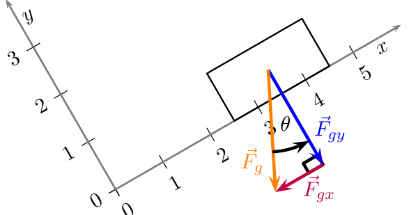
Understanding Force Components:
The mathematical relationships are:
- Component parallel to the plane:
- Component perpendicular to the plane:
Where represents the angle of inclination measured from the horizontal.
These components help you understand how much of the gravitational force tries to slide the object down the plane (parallel component) versus how much presses the object into the surface (perpendicular component).
Worked example: Components of gravitational force
Worked Example: Calculating Force Components on an Inclined Plane
Question: A block experiences a gravitational force of 137 N on an inclined plane. If the slope makes a 37° angle with the horizontal, calculate the force components parallel and perpendicular to the slope.
Solution:
Step 1: Identify the known information
- Total gravitational force: N
- Inclination angle:
- Required: Force components parallel and perpendicular to the slope
Step 2: Apply component formulas
- Parallel component:
- Perpendicular component:
Step 3: Calculate the parallel component
Step 4: Calculate the perpendicular component
Step 5: State the final answer
- The component perpendicular to the slope equals 109.41 N (pressing into the surface)
- The component parallel to the slope equals 82.45 N (sliding down the slope)
Exam tips
Essential Exam Success Strategies:
- Always start with a clear, large diagram - this prevents calculation errors
- Label every force completely - incomplete labelling loses marks
- Check that your components make physical sense - the parallel component should be smaller than the total force for angles less than 45°
- Remember SOH-CAH-TOA - sine gives you the opposite side (parallel to slope), cosine gives you the adjacent side (perpendicular to slope)
- Include units in all final answers - force measurements require Newtons (N)
Key Points to Remember:
- Force diagrams show all forces acting on an object using arrows that indicate direction and magnitude
- Free body diagrams simplify analysis by showing forces as arrows pointing away from a central dot
- When drawing force diagrams, make them large, clear, and properly labelled with arrows touching the object
- On inclined planes, resolve gravitational force into components:
- Parallel component =
- Perpendicular component =
- Always check your trigonometry - sine relates to the parallel component, cosine to the perpendicular component