Plans (Grade 12 NSC Matric Mathematical Literacy): Revision Notes
Plans
Plans are technical drawings and diagrams that help us understand how things are built, assembled, or laid out. They use standardised symbols and representations to communicate important information clearly and accurately.
Plans are technical drawings and diagrams that serve as universal communication tools in construction, assembly, and design. They provide essential information for builders, assemblers, and anyone who needs to understand spatial relationships and construction details.
Assembly diagrams and instructions
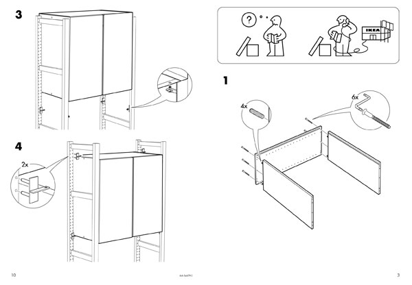
When you purchase items that need to be put together, like furniture or electronic equipment, they come with guidance to help you assemble them correctly. This guidance comes in two main forms:
Assembly instructions are written descriptions that explain each step of the assembly process. These are usually short, clear sentences that tell you exactly what to do at each stage.
Assembly diagrams are annotated pictures that show you visually how to assemble an item. These diagrams use numbered steps and labels to explain the process in detail.
Both types of guidance work together to ensure you understand each symbol and step in the assembly process. It's essential to follow both the written instructions and the visual diagrams carefully to avoid mistakes.
The combination of visual and written instructions ensures that people with different learning styles can successfully complete assembly tasks. Visual learners benefit from the diagrams, while those who prefer step-by-step written guidance can follow the instructions.
Plans and elevations
Understanding building plans requires knowledge of different views and perspectives. Buildings are complex three-dimensional structures, so architects and builders use various views to show all the necessary information.
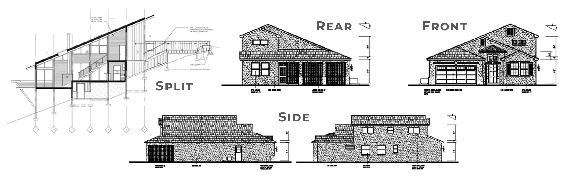
Elevations are drawings that show the front, back, or side view of a building. They help you understand what the building looks like from different angles and show important features like windows, doors, and the roofline.
Technical Annotations in Elevations:
Building elevations typically include important technical information such as:
- FFL 150 NGL: This means Finished Floor Level is 150mm above Natural Ground Level
- Window and door dimensions (shown as width × height measurements)
- Building materials and construction details
The Three Main Types of Elevations:
- Front elevation: Shows the main entrance side of the building
- Side elevation: Shows the building from the side
- Rear elevation: Shows the back of the building
Each elevation provides specific information that cannot be fully understood from other views, making all three types essential for complete building documentation.
Symbols on floor plans
Floor plans use standardised symbols to represent different building elements. Learning these symbols is crucial for reading architectural drawings correctly.
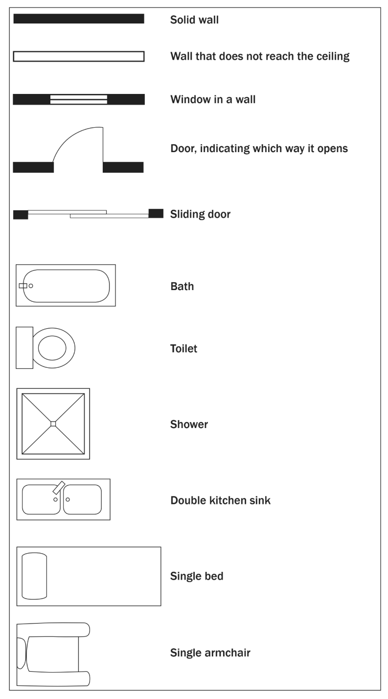
Wall types
- Solid walls: Shown as thick black lines
- Partial walls: Shown as thinner lines that don't reach the ceiling
Doors and windows
- Windows: Represented by three parallel lines within a wall
- Doors: Shown with an arc indicating the direction they open
- Sliding doors: Depicted with parallel lines showing the sliding track
Fixtures and fittings
These are built-in items that are permanent parts of the building:
-
Bath: Oval shape with drain indication
-
Toilet: Circular shape
-
Shower: Square with diagonal lines
-
Kitchen sink: Rectangular shape with divider for double sinks
-
Bedroom furniture: Simple outlines showing beds and chairs
Master These Symbols for Success
Understanding floor plan symbols is fundamental to reading any architectural drawing. These symbols are used consistently across different types of buildings and construction projects, so learning them once will serve you throughout your studies and career.
Reading floor plans
Floor plans contain a wealth of information about building layouts. To read them effectively, you need to understand several key concepts and develop a systematic approach to interpreting the drawings.
Key information to look for
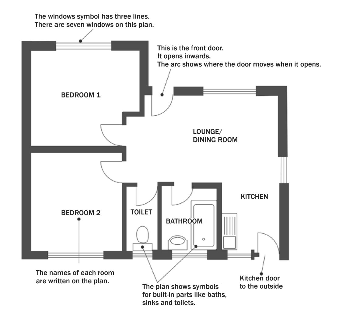
Room names and labels: Each room is clearly labelled to show its purpose (bedroom, kitchen, bathroom, etc.).
Windows and doors: Windows appear as three parallel lines in walls, while doors show both the opening and the arc indicating which way they swing.
Built-in fixtures: Permanent items like toilets, baths, and sinks are shown using standard symbols.
Understanding the Floor Plan Perspective
Floor plans are drawn as if the roof has been removed and you're looking down into the building from above. This bird's-eye view shows the complete layout and how rooms connect to each other.
Important details
When reading floor plans, pay attention to these crucial elements:
- The front entrance helps you identify the building's orientation
- Door swing arcs show which rooms doors open into
- Windows provide information about natural light and ventilation
- Kitchen doors often lead to outside areas for convenience
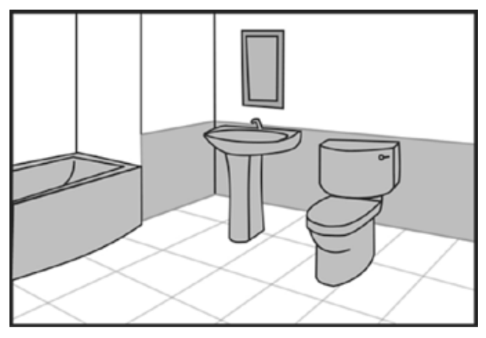
Worked Example: Drawing a Floor Plan
When creating a floor plan from a room illustration, you need to:
Step 1: Identify all fixtures and their positions
- Locate permanent items like toilets, sinks, and baths
- Note their relationships to walls and each other
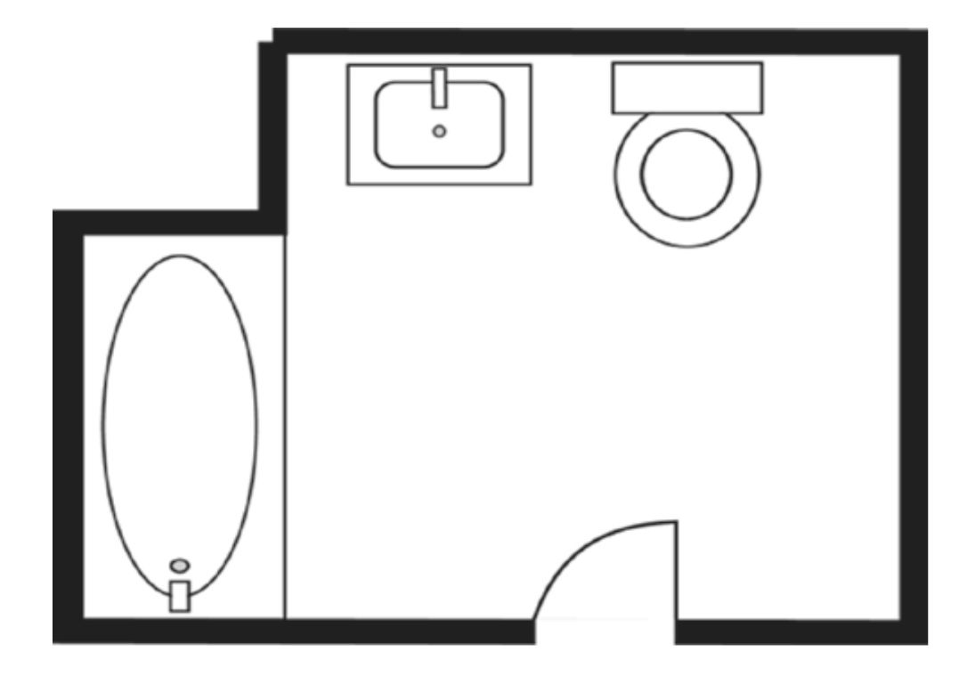
Step 2: Use appropriate symbols for each item
- Apply the standardised symbols you've learned
- Ensure proper proportions and positioning
Step 3: Show wall thicknesses correctly
- Draw walls as thick lines, not thin single lines
- Distinguish between load-bearing and partition walls
Step 4: Add doors and windows in logical positions
-
Show door swing arcs accurately
-
Position windows to provide appropriate light and ventilation
Understanding spatial relationships and the logical flow between rooms is essential when interpreting or creating floor plans. Consider how people will move through the space and whether the layout serves its intended purpose effectively.
Exam tips for plans
Essential Exam Strategies
- Learn the symbols: Memorise the standard symbols for walls, doors, windows, and fixtures
- Check orientations: Always identify the front entrance to understand building orientation
- Look for logical layouts: Kitchens usually connect to outside areas, bathrooms need plumbing access
- Pay attention to measurements: FFL and NGL markings give important height information
- Consider practicality: Question whether door openings and room layouts make practical sense
Key Points to Remember:
-
Assembly instructions use both written descriptions and visual diagrams to guide you through putting items together step by step
-
Elevations show buildings from different sides (front, rear, side views) and include technical measurements like FFL (Finished Floor Level) above NGL (Natural Ground Level)
-
Floor plan symbols are standardised - windows have three lines, doors show swing arcs, and fixtures like toilets and baths use specific shapes
-
Floor plans are viewed from above as if the roof is removed, showing room layouts, connections, and built-in fixtures
-
Reading plans effectively requires understanding orientations, checking that layouts make practical sense, and recognising all the standard architectural symbols