Scale Drawing (HSC SSCE Mathematics Standard): Revision Notes
Scale Drawing, Plans, and Elevations
What is a scale drawing?
A scale drawing represents a real object at a different size, usually smaller, to make it easier to work with on paper. The most common example of a scale drawing is a map, which shows a large area like a country or city in a size that fits on a page.

Maps are the most familiar type of scale drawing we encounter in everyday life. When you use a map on your phone or a paper map, you're working with a scale drawing that shows distances that would be impossible to represent at their actual size.
The scale factor is the ratio that compares the size of the drawing to the actual size of the object. For instance, on a map, cm on the paper might represent km in real life.
Two ways to express scale
Scale can be written in two different ways:
- Using units: For example, cm to m or cm m
- This tells you directly what measurement on the drawing represents in reality
- The first measurement is always the drawing size
- The second measurement is always the actual size
- Using a ratio (no units): For example,
- This means the actual distance is times the drawing distance
- Both measurements must be in the same units
- The ratio means unit on the drawing equals units in reality
When using a ratio scale like , both measurements must be in the same units. You cannot compare centimetres to metres directly - convert everything to the same unit first!
Key formula:
Working with scales
When working with scale drawings, you need to convert between the drawing measurements and the actual measurements.
Finding the actual length
To find the actual length when you know the drawing length:
- Multiply the drawing length by the scale factor
Finding the drawing length
To find the drawing length when you know the actual length:
- Divide the actual length by the scale factor
Memory aid: "Times to find actual, Divide to find drawing"
Think of it this way: the actual object is bigger than the drawing, so you multiply to make it bigger. The drawing is smaller than the actual object, so you divide to make it smaller.
Exam tip: Always check your units carefully. You may need to convert between millimetres, centimetres, and metres to get the answer in the required units. A common mistake is forgetting to convert units at the end!
Worked Example: Using a scale
A scale drawing has a scale of .
a) Find the actual length if the drawing length is mm. Answer to the nearest centimetre.
b) Find the drawing length if the actual length is m. Answer to the nearest millimetre.
Solution:
Part a:
-
The scale means the actual length is times larger than the drawing length
-
Actual length mm
-
Actual length mm
-
Convert to centimetres: cm
-
Answer: cm
Part b:
-
The scale means the drawing length is times smaller than the actual length
-
Drawing length m
-
Drawing length m
-
Convert to millimetres: mm
-
Answer: mm
Plans and elevations
When creating technical drawings, we often need to show different views of a three-dimensional object. The two main types of views are plans and elevations.
Plan view
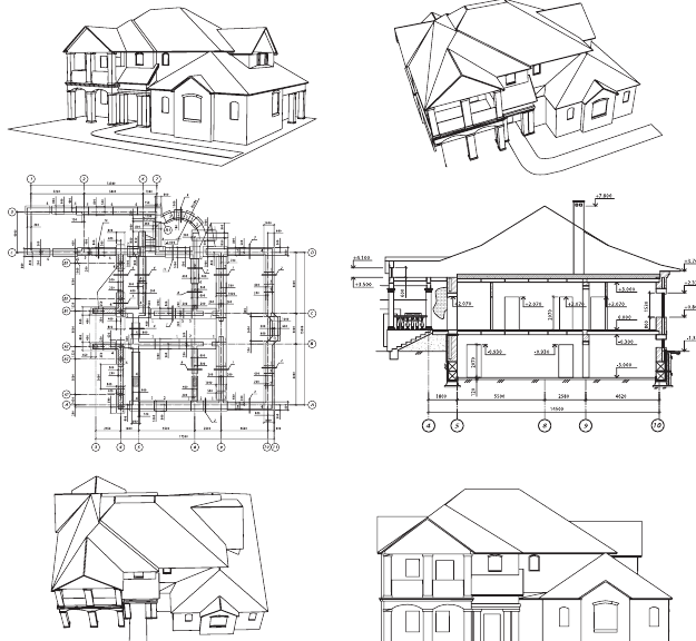
A plan is the view of an object from directly above, looking down on it. For buildings, a floor plan is a horizontal section cut through the building that shows:
- Walls and their thickness
- Windows and doors
- Door openings and which way doors swing
- Fittings and appliances (like toilets, sinks, bathtubs)
- Room layouts and sizes
Elevations
An elevation is the view of an object from one side. Common types include:
- Front elevation: The view from the front of the object
- Side elevation: The view from the side of the object
For buildings, elevations are vertical sections parallel to one side of the building. They show what the building looks like from different directions, including features like windows, doors, roof shape, and external details.
Memory aid: "Plan from above, Elevation from the side"
Remember: if you're looking DOWN at something, you're creating a plan view. If you're looking at something from the SIDE (at eye level), you're creating an elevation.
Worked Example: Drawing plans and elevations
Draw the plan view, front elevation, and side elevation of this object:
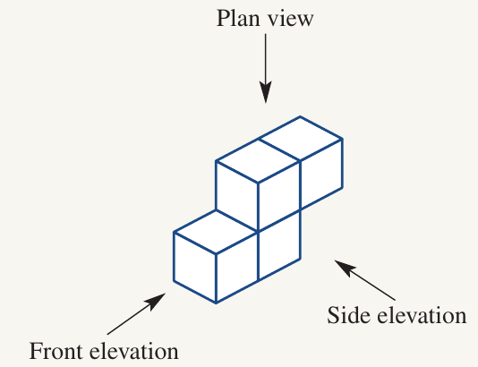
Solution:
To create these different views, imagine looking at the object from different positions:
- Plan view: Look directly down on top of the object
- Front elevation: Look at the object from the front
- Side elevation: Look at the object from the side
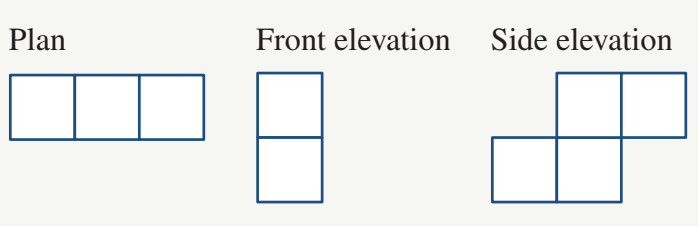
Each view shows only the outline and edges you would see from that particular viewing position. Hidden edges are not shown in these simple elevation drawings.
Building plans
Floor plans are a practical and important use of scale drawings. They allow architects, builders, and homeowners to see the layout of a house and calculate dimensions.
Understanding floor plans
Building plans typically use a scale such as . This means:
- Every cm on the floor plan represents cm (or m) in the actual building
- You can measure the plan with a ruler and multiply by to find real dimensions
The scale is commonly used for residential floor plans because it provides a good balance - the drawings are detailed enough to show all important features while being small enough to fit on standard paper sizes.
Common floor plan symbols
Floor plans use standard symbols to represent different features. Here are the most common ones:
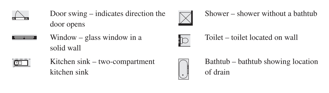
Learning these symbols helps you quickly read and understand floor plans.
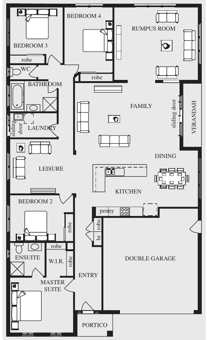
Worked Example: Finding measurements from a floor plan
A building plan is shown for the ground floor of a home.
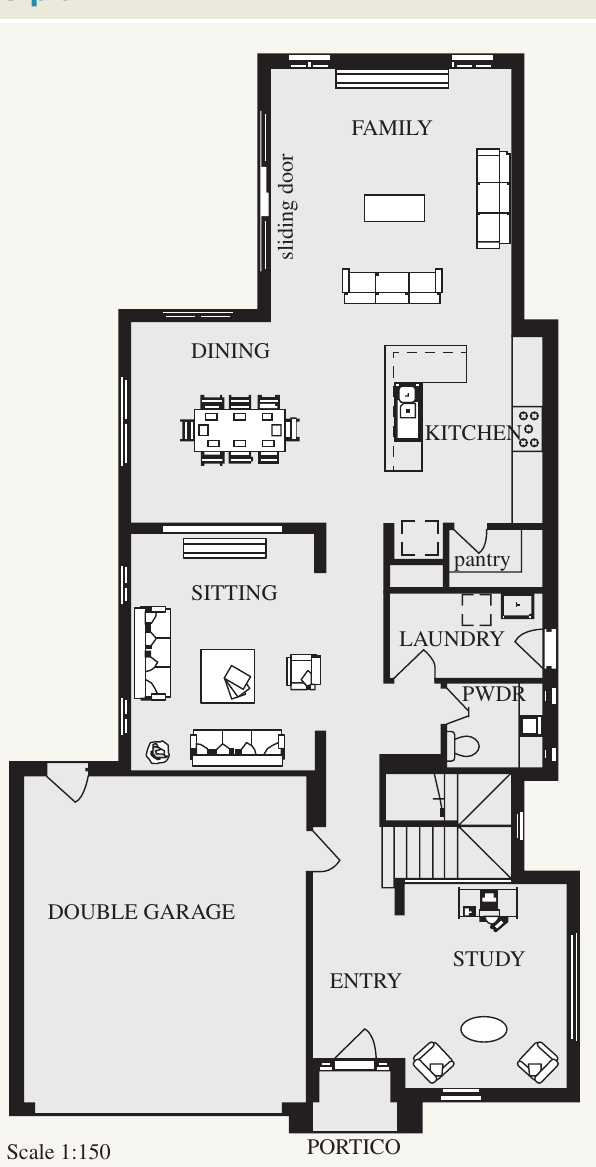
The scale is .
a) How many internal doors are there?
b) What is the meaning of PWDR?
c) What is the length of the house?
d) What are the dimensions of the double garage?
Solution:
Part a:
-
Count the door swing symbols inside the house (not including the garage door or external doors)
-
Answer: 4 internal doors
Part b:
-
PWDR is a common abbreviation used on floor plans
-
Answer: Powder room (a small bathroom with toilet and sink, but no shower or bath)
Part c:
-
Using a ruler, measure the total length of the house on the floor plan
-
Drawing length cm
-
Multiply by the scale factor: Actual length cm
-
Actual length cm
-
Convert to metres: m
-
Answer: m
Part d:
-
Measure the length and width of the double garage on the floor plan
-
Drawing dimensions cm cm
-
Multiply each dimension by :
-
Actual length cm m (to 1 decimal place)
-
Actual width cm m (to 1 decimal place)
-
Answer: m m
Exam tip: When measuring floor plans, use a ruler carefully and measure in centimetres. Always show your working by writing down the drawing measurement before multiplying by the scale factor. This ensures you get method marks even if your final answer is slightly off due to measurement errors.
Key Points to Remember:
-
A scale drawing represents a real object at a different size using a scale factor expressed as a ratio (like ) or with units (like cm m)
-
To find the actual length: multiply the drawing length by the scale factor. To find the drawing length: divide the actual length by the scale factor
-
A plan view shows an object from above, while an elevation shows an object from the side (front elevation, side elevation, etc.)
-
Floor plans are scale drawings that show the layout of a building from above, using standard symbols for doors, windows, and fixtures
-
Always check your units carefully and convert between mm, cm, and m as needed to give your answer in the required form