Electric Circuits (HSC SSCE Physics): Revision Notes
Circuits and Circuit Diagrams
What are circuit diagrams?
Circuit diagrams are visual representations used to show how various components in an electrical circuit are connected together. Unlike a photograph or realistic drawing, a circuit diagram uses standardised symbols to represent each component, similar to how a train network map shows connections rather than exact physical locations.
Think of a circuit diagram like a subway map - it doesn't show the exact physical layout, but rather the relationships and connections between different points. This makes it much easier to understand how the system works without getting distracted by unnecessary details.
The key purpose of a circuit diagram is to show the relationships between components and how they are connected, rather than their actual physical sizes or positions. This makes circuit diagrams an essential tool for understanding, designing, and analysing electrical circuits.
Circuit symbols
Each type of electrical component has its own unique symbol. Learning these symbols is essential for reading and drawing circuit diagrams. The most commonly used circuit symbols include:
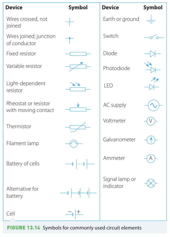
You should familiarise yourself with these symbols as you'll need to recognise them in diagrams and use them when drawing your own circuits. Just like learning the alphabet before reading, mastering these symbols is fundamental to working with electrical circuits.
Drawing circuit diagrams
When drawing a circuit diagram, follow these guidelines:
- Use the correct standardised symbol for each component
- Connect components with straight lines representing wires
- Arrange components in a clear, logical layout (usually rectangular)
- Show the direction of conventional current flow (from positive to negative terminal)
- Ensure all connections are clearly shown
- Wire lengths shown in the diagram don't represent actual wire lengths
Example: Drawing a series circuit
Worked Example: Drawing a Series Circuit
Question: A battery is connected in series with a light globe, a resistor and an ammeter. Draw a circuit diagram for this circuit.
Solution:
The circuit consists of four components connected one after another (in series):
- Battery
- Light globe (filament lamp)
- Resistor
- Ammeter
To draw the diagram, we arrange these components in a single loop, using the correct symbol for each component.
The completed circuit diagram shows all components connected in a continuous path, forming a complete loop.
Practice: Identifying circuit components
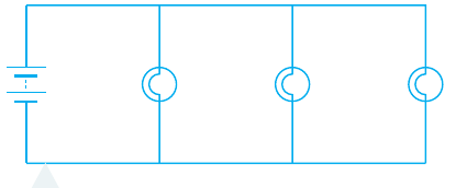
Looking at a circuit diagram, you should be able to identify each component. Consider the following circuit:
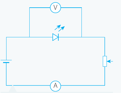
This circuit contains:
- A voltmeter (V) - measures potential difference
- An ammeter (A) - measures current
- An LED (light-emitting diode) - shown with arrows indicating light emission
- A resistor - rectangular symbol
- A battery - provides electrical energy
Kirchhoff's laws and conservation principles
Two fundamental conservation principles help us analyse circuits: conservation of energy and conservation of charge. When applied to circuits, these are known as Kirchhoff's laws, named after German physicist Gustav Kirchhoff.
Kirchhoff's voltage law - conservation of energy
Kirchhoff's voltage law states that the sum of all potential differences (voltages) around any closed loop in a circuit must equal zero:
This law is based on conservation of energy. When a charged particle travels around a complete loop in a circuit, it must return to its starting point with the same energy it started with. Any energy gained (from a battery) must equal the energy lost (across resistors).
Understanding voltage law with a series circuit
Consider a simple series circuit:
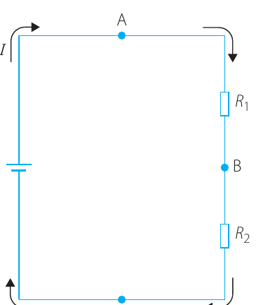
In this circuit, current flows from the battery through resistors and . As charged particles move through each resistor, they lose potential energy, creating a potential difference (voltage drop) across each resistor.
When applying Kirchhoff's voltage law around the loop (from point A → B → C → A):
Or rearranged:
This tells us that the voltage supplied by the battery equals the sum of voltage drops across all resistors in the circuit.
Worked Example: Applying Kirchhoff's Voltage Law
Question: Consider the circuit shown above. The battery supplies a potential difference of 12 V. A voltmeter measures the potential difference across the first resistor () as 3 V. What is the potential difference across ?
Solution:
Given information:
- V
- V
Using Kirchhoff's voltage law around the loop:
Rearranging for :
The potential difference across is 9 V.
Kirchhoff's current law - conservation of charge
Kirchhoff's current law states that the total current entering a junction must equal the total current leaving that junction:
Or equivalently:
This law is based on conservation of charge. Charge cannot accumulate at junctions, nor can it be created or destroyed. Therefore, whatever charge flows into a junction per unit time must flow out in the same time period.
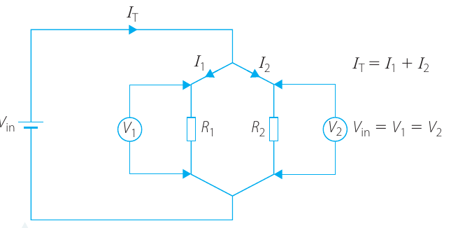
Understanding current law with a parallel circuit
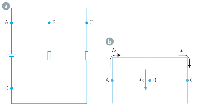
In this parallel circuit, current approaches a junction where it splits into two paths: and . According to Kirchhoff's current law:
At the bottom of the circuit, the currents recombine, so:
Worked Example: Applying Kirchhoff's Current Law
Question: The current at point A in the circuit above is 2.0 A. Three times as much current passes through B as through C. Calculate the currents at B, C and D.
Solution:
Given information:
- A
Applying Kirchhoff's current law at the junction:
Substituting :
Solving for :
Now finding :
Check: A ✓
At the second junction where B and C meet:
Answer: A, A, A
Important principle: Current in series circuits
A crucial consequence of Kirchhoff's current law is that current is constant throughout a series circuit. Since there are no junctions in a single-loop circuit, the same current flows through every component. Current is not "used up" as it passes through resistors or other components - it remains constant around the entire loop.
Series and parallel circuits
There are two main types of circuit configurations: series circuits and parallel circuits. Understanding the difference is essential for circuit analysis.
Series circuits
A series circuit has only one path for current to flow through. All components are connected one after another, end to end, forming a single continuous loop.
Key characteristics of series circuits:
- Same current flows through all components
- Total voltage is divided among components
- If one component fails, the entire circuit breaks

Resistors in series
When resistors are connected in series, we can calculate the total equivalent resistance. Starting with a circuit containing resistors and in series:
The total voltage across both resistors is:
Since the same current flows through both resistors, we can divide by :
Using Ohm's law ():
For any number of resistors in series:
The total resistance of resistors in series is simply the sum of all individual resistances. Adding more resistors in series increases the total resistance and decreases the current.
Worked Example: Series Resistors
Question: A 6 V battery is connected to two resistors in series: Ω and Ω.
Calculate:
- The total resistance
- The current through the circuit
- The potential difference across each resistor
Solution:
Part 1: Total resistance
Part 2: Current through circuit
Using Ohm's law for the total circuit:
Rearranging:
Part 3: Potential difference across each resistor
For :
For , we can use either Ohm's law or Kirchhoff's voltage law:
Using Kirchhoff's voltage law:
Answers: Total resistance = 12 Ω, Current = 0.5 A, V, V
Parallel circuits
A parallel circuit has multiple paths for current to flow through. Components are connected side by side, with multiple branches.
Key characteristics of parallel circuits:
- Current divides among the different paths
- Same voltage across all parallel components
- If one component fails, current can still flow through other paths
Resistors in parallel
When resistors are connected in parallel, they all have the same potential difference across them. Using the circuit shown:
For a parallel circuit with two resistors:
- Voltage is the same:
- Total current divides:
Using Ohm's law for each resistor:
For the total circuit:
Substituting into Kirchhoff's current law:
Since in a parallel circuit:
For any number of resistors in parallel:
For parallel resistors, we add the reciprocals (1/R values). The total resistance is always less than the smallest individual resistor. Adding more resistors in parallel decreases total resistance and increases total current.
Worked Example: Parallel Resistors
Question: For the circuit shown below with two parallel resistors ( Ω and Ω) connected to a 9 V battery, calculate:
- The total equivalent resistance
- The current through the battery
- The current through each resistor
Solution:
Part 1: Total resistance
Finding a common denominator:
Part 2: Current through battery
Part 3: Current through each resistor
For :
For , using Kirchhoff's current law:
Answers: Total resistance = 6 Ω, Total current = 1.5 A, A, A
Important observation: Notice that the total resistance (6 Ω) is less than either individual resistor (9 Ω or 18 Ω). This is always true for parallel resistors. Also, more current flows through the path with lower resistance (), demonstrating that current divides in inverse proportion to resistance.
Practical investigation: Series and parallel circuits
Understanding the behaviour of series and parallel circuits is enhanced through practical investigation. A typical investigation involves:
Aim: To investigate light globes and resistors connected in series and parallel
Part 1: Observing light globes
Compare the brightness of globes connected in:
- Series configuration
- Parallel configuration
Part 2: Measuring resistor properties
For resistors in both series and parallel configurations, measure:
- Current through the circuit
- Voltage across individual resistors
- Calculate total resistance using Ohm's law
Expected observations:
| Configuration | Brightness/Current | Voltage | Total Resistance |
|---|---|---|---|
| Series | Dimmer/Lower | Divided among resistors | Sum of resistances (increases) |
| Parallel | Brighter/Higher | Same across all resistors | Less than smallest resistor (decreases) |
Analysis: Plot graphs of current versus number of resistors to observe:
- Series: Current decreases as more resistors are added
- Parallel: Current increases as more resistors are added
Key Points to Remember
-
Circuit diagrams use standardised symbols to show how components are connected, focusing on relationships rather than physical layout
-
Kirchhoff's voltage law: The sum of potential differences around any closed loop equals zero () - based on conservation of energy
-
Kirchhoff's current law: Current entering a junction equals current leaving () - based on conservation of charge
-
Series circuits have one path; current is the same throughout but voltage divides:
-
Parallel circuits have multiple paths; voltage is the same across all branches but current divides:
-
Current is never "used up" in a circuit - it flows continuously and is conserved