Current-Voltage Relationships (HSC SSCE Physics): Revision Notes
Current-Voltage Relationships
Introduction
For electric current to flow in a circuit, three essential conditions must be satisfied. First, there must be charged particles that are free to move, known as free charge carriers. In metal conductors, these are typically electrons. Second, there must be a continuous conducting path along which these charges can travel. Third, there must be a force to initiate and maintain the movement of these charges.
These three conditions - free charge carriers, conducting path, and driving force - are fundamental requirements for any electrical circuit to function.
One way to provide this force is through an electric field. Electric fields are particularly useful for this purpose because they store potential energy, which can be converted into the kinetic energy of moving charges.
Understanding potential difference
When a charged particle exists within an electric field, it experiences a force. If this particle moves through the field, work is done on the particle by the field. This work results in a change in the particle's energy.
The relationship between the work done and the movement of charge is described by potential difference. The potential difference, , between two points is defined as:
where:
- is the potential difference between two points (measured in volts, V)
- is the work done (measured in joules, J)
- is the charge that moves between the points (measured in coulombs, C)
While the term 'potential difference' is technically more accurate, the term voltage is commonly interchangeable in practice.
The unit of potential difference is the volt (V), which can be expressed as:
This means that one volt represents the change in energy per unit charge as the charge carrier moves through the potential difference.
Energy changes in circuits
Power supplies and batteries provide energy to circuits by performing work on charged particles. When a charge moves between two points in a circuit, it experiences an energy change equal to:
The direction and magnitude of this energy change depends on the component:
- When charge moves through an energy source (such as a battery), it gains energy
- When charge moves through other circuit components (such as resistors or light globes), it typically loses energy
A positive potential difference indicates movement from a less positive (or more negative) point to a more positive (or less negative) point. When a positive charge moves through a positive potential difference, it gains potential energy because it moves against the direction of the electric field lines. This is why conventional current flows through a battery from the negative terminal to the positive terminal.
Measuring potential difference with voltmeters
Potential difference is measured using an instrument called a voltmeter. A voltmeter determines the difference in electric potential between two specific points in a circuit.
The correct way to connect a voltmeter is in parallel with the component across which you wish to measure the voltage. This means the voltmeter is connected to two different points in the circuit simultaneously, allowing it to measure the potential difference between these points. The voltmeter has high internal resistance so that it draws minimal current from the circuit being measured.
Resistance and Ohm's law
What is resistance?
When a battery is connected to a wire, current flows through the wire. However, even excellent conductors like metal wires provide some opposition to current flow. This opposition is called resistance. The only materials that have zero resistance are superconductors, which must be maintained at very low temperatures.
Resistance is a quantitative measure of how much a circuit component opposes the flow of electric current through it. Every component in a circuit contributes some resistance.
Resistance, , is mathematically defined as the ratio of potential difference across a component to the current flowing through it:
where:
- is resistance (measured in ohms, Ω)
- is potential difference across the component (measured in volts, V)
- is current through the component (measured in amperes, A)
The unit of resistance is the ohm (Ω), which is equivalent to (volts per ampere). The ohm is named in honour of Georg Ohm, a German scientist who studied electrical circuits.
This equation reveals an important relationship: for a given applied potential difference, a low current indicates high resistance, while a high current indicates low resistance.
For an insulator, the resistance is extremely high—effectively infinite. Consequently, the current through an insulator is zero. For a good conductor, the resistance is very low, allowing a large current to flow.
Resistors
Components specifically designed to provide a constant, known resistance value in a circuit are called resistors. However, it is important to remember that all circuit components possess some resistance, even if providing resistance is not their primary function.
Worked example: Calculating work done on a charge
Worked Example: Energy Change of an Electron
Let's examine how to calculate the work done when a charge moves through a potential difference.
An electron moves through a potential difference of .
Find the work done on the electron.
Step 1: Identify the relevant values
Step 2: Choose the formula
Use the relationship between voltage, work, and charge:
Step 3: Rearrange the formula
Make the subject:
Step 4: Substitute the values
Step 5: Calculate
Since :
Step 6: Give the final answer
The electron has lost .
This example demonstrates how to use the relationship to determine energy changes. Notice that the negative result indicates the electron has lost energy, which is consistent with an electron moving through a positive potential difference.
Worked example: Calculating current using Ohm's law
Worked Example: Calculating Current
Now let's see how to calculate current when we know the voltage and resistance.
Step 1: Identify the relevant values
Step 2: Choose the formula
Use Ohm’s Law:
Step 3: Rearrange the formula
Make the subject:
Step 4: Substitute the values
Step 5: Calculate
Since :
Step 6: Give the final answer
This example shows the practical application of rearranging the resistance formula to find current:
Ohmic and non-ohmic components
All circuit components can be classified based on how their resistance behaves as voltage changes. This classification helps us predict and understand circuit behaviour.
Ohmic components
Components for which the resistance remains constant over a wide range of applied voltages are called ohmic components. For these components:
This special case, where resistance is constant, is known as Ohm's law. In ohmic components, current is directly proportional to the applied voltage (potential difference).
If we plot a graph of current versus potential difference for an ohmic component, we obtain a straight line passing through the origin. The resistance of the component can be calculated from the gradient of this line:
Therefore:
Metal wire resistors at constant temperature are typical examples of ohmic components.
Non-ohmic components
Components that have resistance varying with applied voltage are called non-ohmic components. These components cannot be characterized by a single constant resistance value.
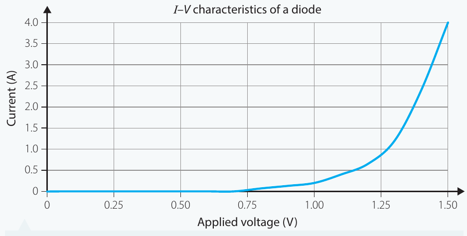
For example, diodes function as one-way valves in circuits. They have very low resistance above a certain minimum voltage (called the threshold voltage) and very high resistance below this voltage. This makes their I-V characteristics distinctly non-linear.
Current-voltage (I-V) characteristic graphs
Current-voltage graphs (also called I-V graphs) are commonly used to represent the electrical characteristics of circuit components. These graphs plot current (on the vertical axis) against potential difference (on the horizontal axis).
Different types of components produce very different I-V graph shapes:
- Ohmic components: produce a straight line through the origin
- Non-ohmic components: produce a curved line
Finding resistance from I-V graphs
For non-ohmic components, we need an I-V graph to determine how the component will behave in a circuit. To find the resistance at a specific voltage:
- Locate the voltage value of interest on the horizontal axis
- Read the corresponding current value from the graph
- Calculate resistance using:
Worked example: Resistance of a diode from an I-V graph
Worked Example: Determining Diode Resistance
The following example demonstrates how to determine the resistance of a non-ohmic component (a diode) at different voltages.
Step 1: Choose the formula
Use Ohm’s Law:
Step 2: Read values from the graph
- At ,
- At ,
- At ,
Step 3: Calculate the resistance for each value
For :
For :
For :
Step 4: Present the results
| (V) | (A) | () |
|---|---|---|
| 0.5 | 0 | |
| 1 | 0.2 | 5 |
| 1.5 | 4 | 0.4 |
Step 5: Interpretation
Note the important concept illustrated here: when no current flows at all, the resistance is effectively infinite. This condition is called an 'open circuit' because it is equivalent to physically disconnecting the circuit, leaving no path for charge carriers to flow along.
Investigation: Measuring I-V characteristics
To develop a deeper understanding of ohmic and non-ohmic behaviour, students can conduct a practical investigation comparing a resistor and a light globe.
Aim
To investigate the I-V characteristics of a resistor and a light globe to determine whether each component is ohmic or non-ohmic.
Materials
- 12 V variable DC power supply
- 100 Ω resistor
- 12 V globe in holder
- Ammeter or multimeter (set to measure current)
- Voltmeter or multimeter (set to measure voltage)
- Connecting wires with crocodile clips
Safety considerations
| WHAT ARE THE RISKS IN DOING THIS INVESTIGATION? | HOW CAN YOU MANAGE THESE RISKS TO STAY SAFE? |
|---|---|
| Electricity can cause shocks. | Keep the power supply turned off until your teacher has checked your circuit. Do not touch the terminals of the power supply when it is turned on. |
Experimental setup
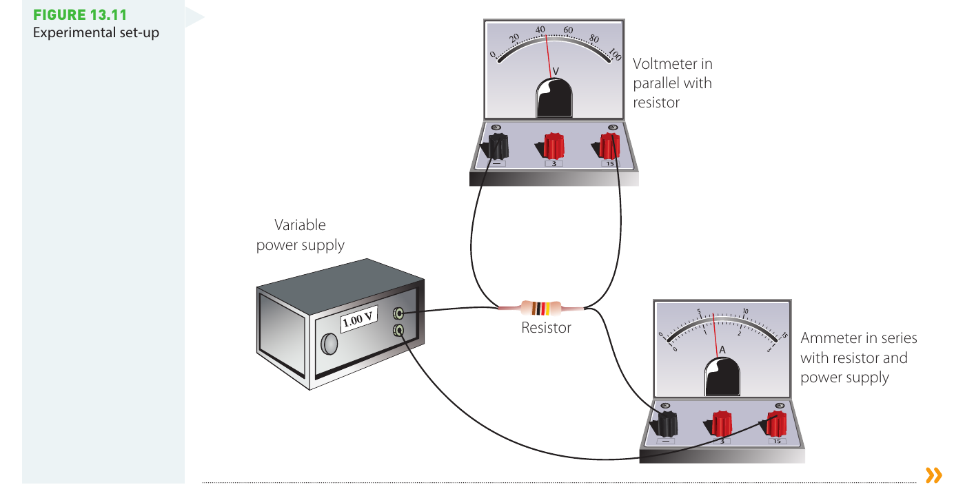
The circuit must be constructed carefully to ensure accurate measurements:
- The ammeter is connected in series with the component being tested and the power supply (to measure current flowing through)
- The voltmeter is connected in parallel across the component being tested (to measure potential difference across)
- The variable power supply allows systematic variation of voltage
Method
The investigation proceeds through these key steps:
- Ensure you understand how to use the meters correctly before beginning
- Construct the circuit with the power supply initially turned off and set to minimum voltage
- Have your teacher check the circuit before turning on the power
- Starting at low voltage (approximately 1 V), record both voltage and current
- Gradually increase the voltage in regular increments (e.g., 1 V steps) up to 12 V
- For each voltage setting, carefully record both the voltage across and current through the component
- Remember to include units and estimated uncertainties in all measurements
- Repeat the entire procedure with the second component
When testing the light globe, it is essential to measure from low voltage to high voltage because the filament's resistance changes significantly as it heats up.
Analysis of results
After collecting data, students should:
- Create scatter plots with current on the vertical axis and voltage on the horizontal axis for each component
- Examine the shape of each graph to identify whether it is linear (ohmic) or curved (non-ohmic)
- For linear graphs, calculate resistance from the gradient
- For non-linear graphs, calculate resistance at each voltage and plot resistance versus applied voltage
Expected outcomes
- The resistor typically shows ohmic behaviour with a linear I-V relationship
- The light globe typically shows non-ohmic behaviour, with resistance increasing as the filament heats up
- Additional observations may include changes in the globe's brightness with increasing voltage
Remember!
Key Points to Remember:
- Potential difference (voltage) is the work done per unit charge when a charge moves between two points:
- Voltage is measured in volts (V), where
- Voltmeters measure potential difference and must be connected in parallel across components
- Resistance is the ratio of voltage to current: , measured in ohms (Ω)
- Ohmic components have constant resistance, producing straight-line I-V graphs; non-ohmic components have variable resistance, producing curved I-V graphs
- The resistance of any component can be determined from its I-V graph by calculating at the voltage of interest