Electric Fields (HSC SSCE Physics): Revision Notes
Electric Fields
Introduction to electric fields
The electric field model explains how charged objects can exert forces on each other without being in contact. Unlike contact forces that only work when surfaces touch, field forces can act over distances. This model was developed from Michael Faraday's idea of 'lines of force', which allow one object to influence another some distance away.
The electric field model assumes charges are stationary and ignores quantum or relativistic effects. Despite these simplifications, it accurately predicts the behavior of most interacting charged objects.
All objects with electric charge create an electric field around themselves. Any charged object placed in this field will experience a force.
Definition of Electric Field
The electric field at any point in space is defined as the force per unit charge that would act on a small positive charge placed at that location. In other words, the field represents how much force would act on a positive charge at each position.
Because the electric field varies from place to place, we always specify "at a particular point" when describing field strength. The field depends only on the charges creating it, not on any test charges we might use to detect it.
Since force is a vector quantity with both magnitude and direction, the electric field is also a vector. Remember that like charges repel and unlike charges attract. Therefore, the field around a positive point charge pushes other positive charges away, meaning the field points radially outward from a positive charge.
Electric field lines
Fields can be visualized using field line diagrams. An electric field line diagram uses lines with arrows to show the direction of force that would act on a small positively charged particle at various points in space.
Constructing field line diagrams
To create a field line diagram, we start by imagining what would happen to a small positive test charge placed at different positions near the charge or charges creating the field. Let's consider a single positive charge. When we place a small positive test charge near it, the test charge will be pushed away because like charges repel. The direction of the electric field points radially away from the positive charge.

By drawing arrows showing the force at many points and then connecting these arrows smoothly, we create field lines. For a single positive point charge, the field lines point radially outward in all directions. If the point charge were negative instead of positive, the field lines would all point radially inward, because a small positive test charge would be attracted toward a negative charge.
Important Pattern:
Field lines originate from positive charges and terminate at negative charges. This pattern exists because positive charges repel positive test charges while negative charges attract them.
Notice that as a test charge moves further from the source charge, the force it experiences becomes weaker. In field line diagrams, this is shown by the lines spreading further apart. In general, when field lines are more widely spaced, the field is weaker and the force is smaller. Conversely, where field lines are close together, the field is strong.
Characteristics of electric field lines
At any single point in space, the force can only point in one direction. If you place a positive charge at a point in an electric field, it will experience a force and accelerate in a specific direction. Since acceleration can only occur in one direction at a time, the force must point in a single direction. This means field lines can never cross. If they did cross, it would incorrectly suggest that the force acts in two different directions simultaneously at the same point.
Key Characteristics of Electric Field Lines:
- They point in the direction of the force acting on a positively charged particle
- They never cross each other
- They originate from positive charges and terminate at negative charges
- Field strength is proportional to the density of field lines (closer lines = stronger field)
Drawing field line diagrams
When drawing a field line diagram, there are infinitely many possible field lines you could draw. However, you need to choose a practical number that clearly shows the field pattern. In general, draw enough lines to reveal what the field looks like around the charges.
Guidelines for Drawing Field Lines:
For a point charge, you should draw at least eight field lines, evenly spaced around the charge. When multiple charges are present, make the ratio of field lines proportional to the magnitude of that charge. This ensures your diagram correctly represents the field strength around each charge.
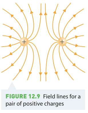
Worked example: pair of equal positive charges
Worked Example: Drawing Field Lines for Two Equal Positive Charges
Problem: Draw a field line diagram for a pair of equal positive charges.
Solution:
Step 1: Imagine placing a small positive test charge at various points around the two positive charges. At each location, consider the force that would act on the test charge due to both charges.
Step 2: Because both charges are positive, they both repel the test charge. Draw arrows showing these repulsive forces at many points around the charges. The net force at each point is the vector sum of the forces from both charges.
Step 3: After drawing force arrows at numerous points, connect them smoothly to form field lines. The resulting pattern shows field lines radiating outward from each positive charge. Between the two charges, the field lines curve away from each other because the charges repel. At points directly between the charges, the forces from each charge cancel, creating a point of zero field.
Field configurations
Dipoles
A dipole consists of a positive charge and a negative charge of equal magnitude placed close together. This is a common and important charge configuration in physics.
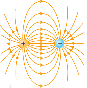
In a dipole, field lines emerge from the positive charge and curve around to enter the negative charge. The field pattern shows the characteristic curved lines connecting the two charges. Real-world examples include the sodium and chlorine atoms in a bound NaCl molecule, which form a dipole.
Polar molecules
Polar molecules have charge separation within them, similar to dipoles. Water (H₂O) is a classic example of a polar molecule. In water, the hydrogen atoms share their electrons with the oxygen atom. This sharing is unequal, making the hydrogen atoms slightly positive and the oxygen atom slightly negative.
The resulting electric field pattern around a water molecule resembles that of a dipole, with field lines emerging from the positive regions (hydrogens) and entering the negative region (oxygen). This polarity is responsible for many of water's unique properties.
Uniform electric fields
Definition of Uniform Electric Field
A uniform electric field is one that has constant magnitude and direction at all points in space. Unlike the radial fields around point charges, uniform fields don't vary from place to place within a specified region.
Single large charged sheet
We can create a uniform electric field using a single, very large, uniformly charged plate. Consider what happens when we place a small positive test charge at different positions near a large flat positively charged sheet.
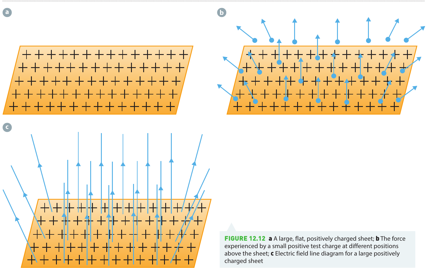
At any position above the sheet, the force on the test charge points directly away from the sheet (upward for a positively charged sheet). When we draw field lines, they must remain parallel to avoid crossing. This tells us that as we move further above the sheet, the field remains constant in both magnitude and direction - it is uniform.
The field lines are parallel above most of the sheet but spread apart at the edges. The field is only truly uniform away from the edges of the sheet. Near the edges, the field becomes weaker and non-uniform.
Parallel plates (capacitors)
To create a strong, uniform electric field over a larger region, we can use two parallel plates with opposite charges. The field between the plates is uniform throughout most of the region, becoming non-uniform only very close to the edges.
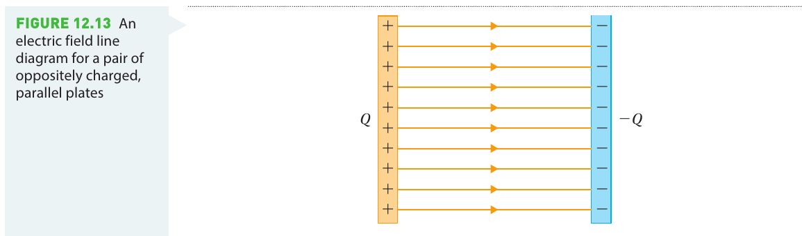
This arrangement is called a capacitor and is widely used in electric circuits for storing energy. The uniform field between the plates provides predictable forces on charged particles placed in this region.
Worked example: forces in uniform fields
Worked Example: Particle Acceleration in Uniform Fields
Problem: A proton and a dipole are placed between charged parallel plates as shown. In which direction will each object accelerate? Explain your answer.
Solution:
Part a: A proton
Step 1: Identify the field direction The electric field lines point from left to right (from the positive plate toward the negative plate).
Step 2: Determine the force direction A proton carries positive charge. Electric field lines indicate the direction of force on a positive charge.
Step 3: Apply Newton's second law Since force and acceleration are in the same direction, the proton will accelerate to the right (toward the negative plate).
Part b: A dipole
Step 1: Analyze forces on each end A dipole has equal amounts of positive and negative charge. The negative portion experiences a force to the left (toward the positive plate), while the positive portion experiences an equal force to the right (toward the negative plate).
Step 2: Calculate net force These two forces are equal in magnitude but opposite in direction, so the net force on the dipole is zero.
Step 3: Determine acceleration With zero net force, the dipole does not accelerate.
Dipole behavior in uniform fields
Although a dipole experiences zero net force in a uniform electric field, it is not unaffected by the field. The forces on the positive and negative ends of the dipole are not along the same line. This creates a torque that causes the dipole to rotate, attempting to align itself with the field lines.
Attraction of neutral objects
When a charged object attracts a neutral object, temporary dipoles form in the neutral object. The atoms and molecules distort slightly, becoming polarized. For these induced dipoles to experience a net force and be attracted to the charged object, the electric field must be non-uniform - one end of each dipole must experience a stronger force than the other.
Most charged objects produce non-uniform fields, which is why a charged comb can lift uncharged polystyrene beads or tiny pieces of paper. However, a perfectly uniform electric field exerts zero net force on an uncharged object, though it can still cause rotation.
Investigation: drawing electric field lines
Aim: To draw electric field line diagrams for various arrangements of charged particles
Research questions: Write one or more research questions for this investigation.
Materials:
- Computer with internet access
- Access to online simulation
Method:
- Open the 'Charges and fields' simulation
- Use the simulation to draw an electric field line diagram for one positive charge. Make a copy (sketch or screenshot) of the result
- Use the simulation to draw an electric field line diagram for one negative charge. Make a copy
- Use the simulation to draw an electric field line diagram for a dipole. Make a copy
- Use the simulation to draw an electric field line diagram for two positive charges. Make a copy
- Place three positive charges, closely spaced together, in a line. Make a copy of the resultant electric field line diagram
- Add another positive charge to one end of the line
- Repeat step 7 until you have as large a line of closely spaced positive charges as possible. Make a copy of the final result and at least one intermediate result
- Create a line of closely spaced alternating positive and negative charges. Make a copy of the resultant electric field line diagram
Results:
You should collect a series of field line diagrams showing different charge configurations.
Analysis:
- Identify regions of large and small electric field in your diagrams. Look for areas where field lines are densely packed (strong field) versus widely spaced (weak field)
- Examine whether any of your diagrams contain regions of uniform electric field. A uniform field has parallel, evenly spaced field lines
- Describe what happens to the field pattern as you progressively add charges in a line. Note that the simulation shows a two-dimensional cross-section through the three-dimensional field
- The final arrangement (alternating positive and negative charges) represents a polarised neutral material. Describe the characteristics of the resulting electric field
Discussion:
- What general principles can you derive from your observations about field patterns?
- Compare how the electric field varies around a point charge, a dipole, a sheet of charge, and a polarised neutral object. What are the similarities and differences?
- Have you answered your inquiry questions? Review your findings and ensure you've addressed what you set out to investigate
Conclusion:
Write a conclusion summarising your findings about electric field patterns for different charge configurations.
Key Points to Remember:
- The electric field at any point is defined as the force per unit charge acting on a small positive charge at that location
- Electric field is a vector quantity with both magnitude and direction
- Field lines show the direction a positive test charge would be pushed or pulled at each point
- Field lines never cross, originate from positive charges, terminate at negative charges, and indicate field strength by their spacing
- Closer field lines indicate stronger fields; wider spacing indicates weaker fields
- Uniform electric fields have constant magnitude and direction, created by large charged sheets or parallel plates
- In a uniform field:
- Positive charges accelerate in the field direction
- Negative charges accelerate in the opposite direction
- Dipoles experience zero net force but rotate to align with the field