Magnetic Fields Produced by Current-Carrying Wires and Solenoids (HSC SSCE Physics): Revision Notes
Magnetic Fields Produced by Current-Carrying Wires and Solenoids
Introduction
In 1819, Hans Christian Øersted made a groundbreaking discovery: a current-carrying wire creates a magnetic field. This observation revolutionised our understanding of electromagnetism and led to the development of motors, generators, and many other useful devices we use today.
While permanent magnets made from ferromagnetic materials are convenient for producing small magnetic fields, when a large field is needed, we use an electromagnet. An electromagnet consists of a current-carrying coil of wire and can be switched on and off by controlling the current.
The ability to switch electromagnets on and off makes them incredibly versatile. Unlike permanent magnets, electromagnets can be controlled precisely, making them essential in applications from MRI machines to electric motors and magnetic levitation trains.
Different arrangements of current-carrying wires can create magnetic fields of different strengths and shapes. In this note, we'll explore two important configurations: straight wires and solenoids (coils).
Magnetic field due to a current-carrying wire
Key observations by Biot and Savart
Jean-Baptiste Biot and Félix Savart performed extensive experiments with magnets and current-carrying wires. They discovered three important relationships for the magnetic field at a point some distance from a long straight current-carrying wire:
- Direction: The magnetic field is perpendicular to both the direction of the current and to a line between the wire and point .
- Distance relationship: The magnitude of the field is inversely proportional to the distance from the wire to . This means as you move further from the wire, the field becomes weaker.
- Current relationship: The magnitude of the field is directly proportional to the current. Doubling the current doubles the field strength.
Mathematical formula
These observations can be expressed mathematically as:
where:
- is the magnitude of the magnetic field (in tesla, T)
- is the current in the wire (in amperes, A)
- is the perpendicular distance from the wire (in metres, m)
- is the permeability of free space
The permeability of free space
The constant is called the permeability of free space and has the value:
This constant serves the same function for magnetic fields as the permittivity of free space () does for electric fields. It determines the strength of a field created by a given current in vacuum and ensures the units work out correctly.
The permeability of free space is a fundamental constant in electromagnetism. Just as appears in equations for electric fields, appears in all equations involving magnetic fields. Always use the full value in calculations to maintain accuracy.
Units of magnetic field
Magnetic field is measured in tesla (symbol: T), named after Nikola Tesla who made important contributions to electricity and magnetism. The tesla can be expressed in fundamental SI units as:
A current-carrying wire is a line source of magnetic field, not a point source. This is why the field varies with rather than (which applies to point sources like single charges). This geometric difference is crucial for understanding how magnetic field strength decreases with distance.
Worked example: Calculating field strength
Worked Example: Magnetic Field from a Straight Wire
Given information:
- Current: A
- Distance from wire: cm = m
- Permeability of free space: T m A
Required: Magnetic field strength
Solution:
Using the formula:
Substituting values:
Simplifying:
Answer: The magnetic field strength at 10 cm from the wire is 5.0 μT (microtesla).
Exam tip: Always convert distances to metres before substituting into the formula. Remember that 10 cm = 0.10 m. A common mistake is forgetting this conversion, which will give an incorrect answer by a factor of 100!
Direction of the magnetic field
The magnetic field around a current-carrying wire forms circular loops. To determine the direction of these field lines, we use the right-hand rule (also called the "rule of thumb"):
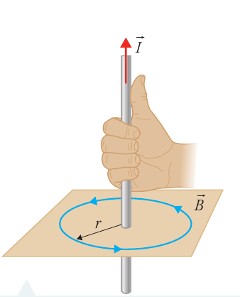
Right-hand rule procedure:
- Point your right thumb in the direction of the current
- Your fingers naturally curl in the direction of the magnetic field lines
Always use your RIGHT hand, not your left. Using the wrong hand will give you the opposite direction for the magnetic field!
When the current is coming towards you (out of the page), the magnetic field lines circle anticlockwise. When the current is going away from you (into the page), the field lines circle clockwise.
Drawing magnetic field lines
When drawing field line diagrams for a current-carrying wire:
- Draw circular loops centred on the wire
- Space the loops further apart as you move away from the wire (since field strength decreases with distance)
- Add arrows to show the direction of the field
- Draw a sensible number of field lines (not too many, not too few)
The density (closeness) of field lines represents field strength—closer lines indicate stronger field.
Magnetic field due to a current-carrying solenoid
What is a solenoid?
A solenoid is a coil of wire wound into a cylindrical shape. It's one of the most effective ways to create a large, uniform magnetic field. By coiling a single wire into many loops, we essentially combine the magnetic fields from each loop to produce a strong total field.
Solenoids are everywhere in modern technology! They're used in door locks, car starters, relay switches, loudspeakers, and even in scientific equipment like particle accelerators. Their ability to create strong, controllable magnetic fields makes them invaluable.
How solenoids create magnetic fields
Each loop of wire in the solenoid creates its own circular magnetic field (just like a single wire). Inside the coil, these individual fields add together to produce:
- A large, uniform magnetic field with straight, parallel field lines
- A field strength that increases with the number of turns (loops)
- A very weak field outside the coil
In a tightly wound solenoid (loops close together), the internal field becomes very uniform, with field lines running straight and parallel along the axis of the coil.
Comparison to a bar magnet
The magnetic field pattern of a solenoid is remarkably similar to that of a bar magnet. Just as a bar magnet has north and south poles at its ends, a solenoid also has:
- A north pole at one end
- A south pole at the other end
The field lines emerge from the north pole and curve around to enter the south pole, forming closed loops—just like with a permanent magnet.
Mathematical formula for solenoid field
The magnetic field strength inside a solenoid depends on three factors:
where:
- is the magnetic field strength inside the solenoid (in tesla, T)
- is the permeability of free space ( T m A)
- is the number of turns (loops) of wire
- is the current through the wire (in amperes, A)
- is the length of the solenoid (in metres, m)
The more turns per unit length (), the stronger the magnetic field. This ratio is sometimes called the turn density. This means you can increase the field strength by either adding more turns or compressing the coil into a shorter length.
Worked example: Calculating current in a solenoid
Worked Example: Finding Current in a Solenoid
Given information:
- Magnetic field required: T
- Number of turns:
- Length of solenoid: m
- Permeability of free space: T m A
Required: Current
Solution:
Starting with the solenoid formula:
Rearranging to solve for current:
Substituting values:
Answer: A current of approximately 3.2 A is required to produce the desired magnetic field.
Exam tip: When rearranging the solenoid formula to solve for current, you get . Remember to check that all your units are in SI base units before calculating. This is a common source of errors in exam questions!
Investigation 14.5: Investigating magnetic fields due to currents
This practical investigation allows you to explore the magnetic fields created by different current configurations.
Aim
To investigate the magnetic fields produced by current-carrying wires in different arrangements (straight wire, coil/solenoid, and parallel wires).
Materials
- Magnetic field meter or compass (alternatively, a smartphone with compass and magnetic field meter app)
- DC power supply
- Cardboard tube
- Light globe of same voltage as power supply (e.g. 12 V globe for 12 V supply)
- Insulated wire (at least 2 m long)
- Connectors (such as alligator clips)
- Tape
- At least 1 m of clear bench space
A magnetic field meter allows quantitative measurements of field strength. If using only a compass, you can measure angles of deflection to indicate relative field strength. Modern smartphones often have built-in magnetometers that can measure magnetic field strength with reasonable accuracy.
Risk assessment
Be careful not to set the voltages and currents too high, as there is a danger of electric shock.
Method
- Preparation: If using a magnetic field meter or app, read the instructions and ensure you know how to use it correctly, including whether it needs to be aligned with the field.
- Baseline measurement: Before connecting any equipment, measure the background magnetic field strength (Earth's magnetic field) or note the compass needle direction. Record this result.
- Circuit setup: Connect the wire to the light globe at one end and the power supply at the other. Connect the other terminal of the globe to the power supply to complete the circuit.
Safety Warning: Never connect the wire directly across the power supply without the light globe—the wire has insufficient resistance and will cause a short circuit. The light globe acts as a protective resistor in the circuit.
- Straight wire investigation: Stretch out the wire so you have a straight section well away from the power supply. You may tape a section to the bench to keep it straight.
- Measurement: Turn on the power supply. The light should glow, confirming current flow. Measure the field around the straight wire or note compass deflections. Record how the field varies above and to the sides of the wire. Note the current direction.
- Reverse current: Observe what happens when you reverse the direction of current through the wire.
- Solenoid investigation: Turn off the power and disconnect the wire from the power supply (leave it connected to the light globe). Wrap the wire around the cardboard tube to form a coil, always wrapping in the same direction. Secure with tape. Leave enough wire free to reconnect to the power supply.
- Solenoid measurements: Connect the coiled wire to the power supply. Repeat measurements inside the tube, at its ends, and to the side.
- Parallel wires investigation: Lay the wire back and forth on the bench in parallel lines, taping down as needed.
- Additional investigations: Other wire arrangements can also be explored.
Results
You should have records of the magnetic field for:
- A long straight current-carrying wire
- A solenoid (coil)
- Parallel current-carrying wires
For each configuration, note how the field strength varies with position and how it changes when current direction is reversed.
Expected observations
- Straight wire: Circular field lines around the wire, field strength decreasing with distance
- Solenoid: Strong, uniform field inside the coil; much weaker field outside; field pattern similar to a bar magnet
- Field direction: Reversing current reverses the direction of the magnetic field
Remember!
Key Points to Remember:
-
Current creates magnetism: Any current-carrying wire produces a magnetic field in the surrounding space.
-
Straight wire formula: — field strength decreases with distance ( relationship) and increases with current.
-
Right-hand rule: Point your right thumb along the current direction; your fingers curl in the direction of the magnetic field lines.
-
Solenoid formula: — field strength increases with more turns, higher current, or shorter length.
-
Solenoids are like bar magnets: They have north and south poles at their ends and create similar external field patterns, but with a strong, uniform field inside.
-
The tesla (T): Magnetic field strength is measured in tesla, where .
-
Safety first: When investigating magnetic fields with electric currents, be careful not to set voltages and currents too high to avoid electric shock.