Generators and AC Induction Motors (HSC SSCE Physics): Revision Notes
Generators and AC Induction Motors
Introduction to generators
A generator is a device that converts kinetic energy into electrical energy. It operates on the opposite principle to a motor. While motors transform electrical potential energy into the kinetic energy of rotation, generators convert the mechanical energy of a spinning coil (or armature) into electrical potential energy that drives a current.
Generators are fundamental to modern electricity production. Nearly all the electricity we use comes from generators powered by various energy sources, making them one of the most important technological devices in our energy infrastructure.
The main energy sources that drive generators include:
- Fossil fuels (mainly coal in Australia) provide thermal energy through combustion
- Hydroelectric power stations harness the gravitational potential energy of water
- Wind turbines capture the kinetic energy of moving air
- Nuclear power plants (used in many countries) generate heat from nuclear reactions
All these energy sources ultimately drive generators to produce electricity.
AC generators
Structure and components
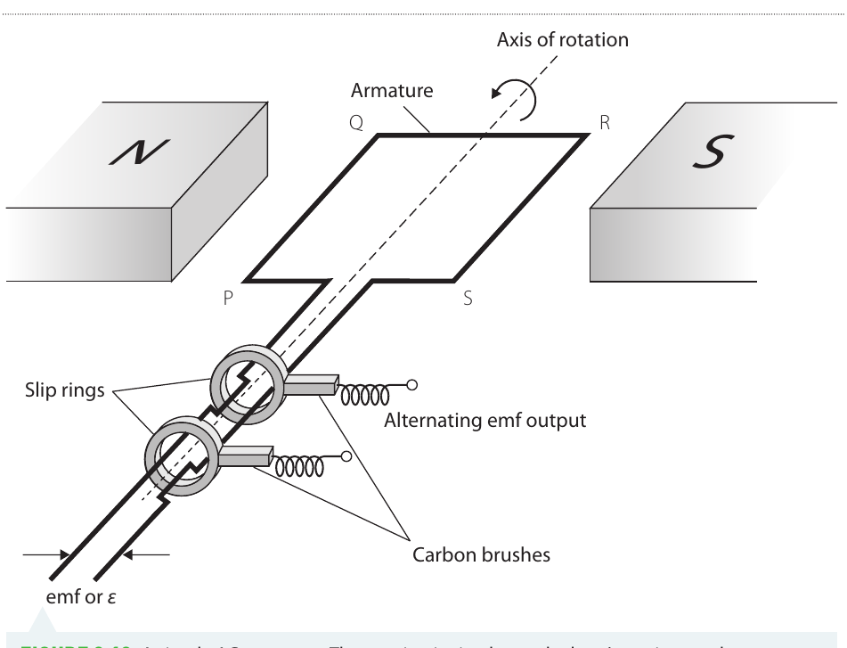
An AC (alternating current) generator produces an electromotive force (EMF) that varies sinusoidally between positive and negative values. The basic structure consists of:
- Armature: A rotating coil positioned between magnetic poles
- Magnetic field: Created by permanent magnets (N and S poles)
- Slip rings: Conducting rings attached to each end of the coil
- Carbon brushes: Contact points that slide against the slip rings and connect to the external circuit
- Axis of rotation: The central shaft around which the armature rotates
Operating principle
As the coil rotates in the magnetic field, the magnetic flux through it changes continuously. According to Faraday's Law, this changing flux induces an EMF across the coil terminals. The slip rings maintain continuous electrical contact through the carbon brushes, allowing the generated EMF to flow to an external circuit.
The slip rings are crucial to AC generator operation - they maintain continuous contact as the coil rotates, unlike the commutator in a DC generator which reverses the connections. This allows the natural alternating nature of the induced EMF to be transmitted to the external circuit.
Mathematical description of flux and EMF
The magnetic flux through a rotating coil varies with time. When the coil has turns, cross-sectional area , and rotates in a magnetic field of strength , the flux varies according to:
where is the frequency of rotation (in Hz) and is time.
The angle of rotation changes with time as , where is the period of one complete rotation. The frequency and period are related by .
According to Faraday's Law, the induced EMF equals the negative rate of change of flux. For our rotating coil, this gives:
This equation shows that the EMF also varies sinusoidally with time, but is phase-shifted relative to the flux.
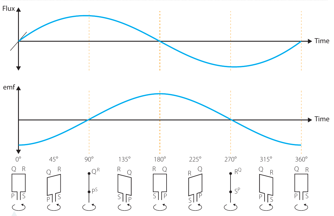
Key relationships between flux and EMF:
- When flux changes most rapidly (steepest gradient), the EMF reaches its maximum values
- When flux is at a peak or trough (gradient = zero), the EMF equals zero
- The flux and EMF have the same frequency but different phases
Understanding this phase relationship is crucial for analyzing AC generator behavior.
Maximum EMF
The maximum EMF occurs when the cosine term equals :
This maximum value depends on:
- : Frequency of rotation (higher frequency → greater maximum EMF)
- : Number of turns in the coil (more turns → greater maximum EMF)
- : Magnetic field strength (stronger field → greater maximum EMF)
- : Cross-sectional area of the coil (larger area → greater maximum EMF)
In practical generators, the armature typically contains many turns of wire to increase the EMF. However, more turns means greater mass, so sometimes the magnets are rotated while the coil remains stationary.
RMS values
For AC quantities, we often use root mean square (RMS) values rather than peak values. The RMS EMF relates to the maximum EMF by:
Similarly, the RMS current (which depends on the load resistance ) is:
RMS values are particularly useful because they represent the effective voltage or current that produces the same power dissipation in a resistor as an equivalent DC value. This is why household power is typically specified as 240 V RMS rather than the peak voltage.
Worked example: calculating maximum EMF
Worked Example: Calculating Maximum EMF
Problem: A square coil of side length m is made up of turns of wire. It rotates at Hz in a magnetic field of magnitude T. Find the maximum EMF induced.
Solution:
Using the formula for maximum EMF:
Substituting values:
- Hz
- turns
- T
- ``````$A = 0.10 \text{ m} \times 0.10 \text{ m} = 0.01 \text{ m}^2$$
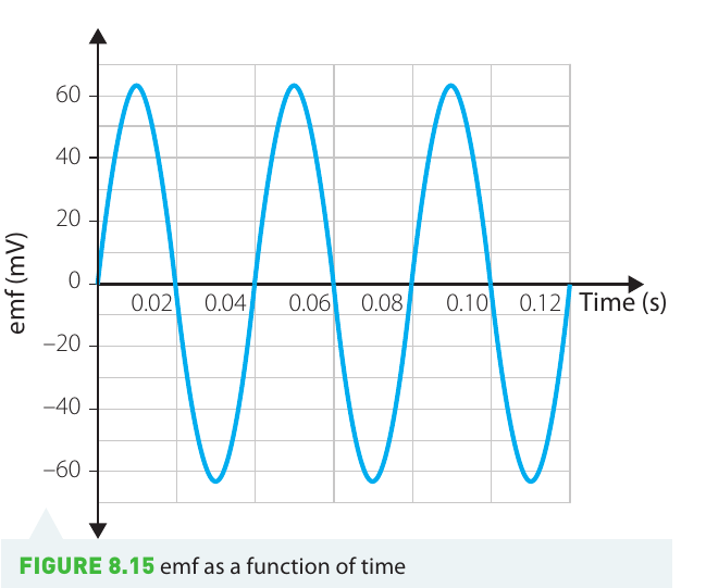
Graph of EMF vs time:
If at there is maximum flux through the coil, the EMF varies as shown below. The period of oscillation is s, meaning the EMF completes one full cycle every seconds.
Worked example: RMS to peak voltage conversion
Worked Example: RMS to Peak Voltage Conversion
Problem: The RMS potential difference produced by an AC generator is V. What is the peak voltage?
Solution:
The relationship between RMS and peak values is:
Rearranging for peak voltage:
Substituting :
This shows that the peak voltage in household mains electricity is significantly higher than the RMS value we commonly refer to.
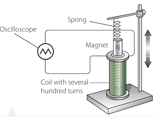
Investigation: a simple AC generator
Aim
To construct a simple AC generator and measure the EMF it produces.
This investigation demonstrates the fundamental principles of electromagnetic induction and allows you to verify the relationship between frequency and maximum EMF experimentally.
Materials
- Retort stand and clamps
- Spring
- Magnet
- Weights
- Alligator leads
- Coil (several hundred turns)
- Oscilloscope or data logger connected to computer
Safety considerations
| What are the risks? | How to manage them |
|---|---|
| The magnet could fly off the spring and hit someone | Ensure the magnet is securely attached and avoid vigorous oscillation |
| Magnets can break or become demagnetised when dropped | Handle magnets carefully and place them down gently when not in use |
Method
- Attach the spring to the retort stand as shown in the diagram
- Secure the magnet and one weight to the spring
- Position the coil below the magnet so that at equilibrium, the magnet sits just inside the coil
- Connect the coil to an oscilloscope or data logger to measure the induced EMF
- Pull the magnet down to start it oscillating (you may need to temporarily move the coil aside)
- Record the period of oscillation and maximum EMF. For better precision, measure the time for ten complete oscillations, then divide by
- Repeat measurements with different weights to vary the oscillation frequency, adjusting the spring height each time
Results
Record your measurements in a table with uncertainties:
| Time for ten oscillations | Period | Frequency | Maximum emf |
|---|---|---|---|
Analysis
Plot a graph of maximum EMF against frequency of oscillation. The relationship should be approximately linear, consistent with the equation .
Discussion
Compare your results with the theoretical prediction. Consider sources of uncertainty and how the experiment could be improved or extended.
DC generators
Commutator design
A DC (direct current) generator produces an output EMF that remains positive (or always negative) rather than alternating. This is achieved by using a commutator instead of slip rings.
In a commutator:
- Each side of the coil connects to a separate conducting copper strip
- The strips are separated by insulators
- As the commutator rotates past the carbon brushes, the connections effectively reverse every half-cycle
- This converts the alternating EMF in the coil into a pulsed DC output
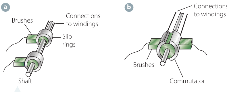
The commutator is essentially a mechanical rectifier - it converts AC into DC by switching the connections at precisely the right moments. This happens automatically through the rotation of the commutator segments past the stationary brushes.
Single coil vs multiple coils
A single-coil DC generator produces a "lumpy" output that rises to a maximum and falls back to zero each half-turn. This fluctuating output is often unsatisfactory for practical applications.
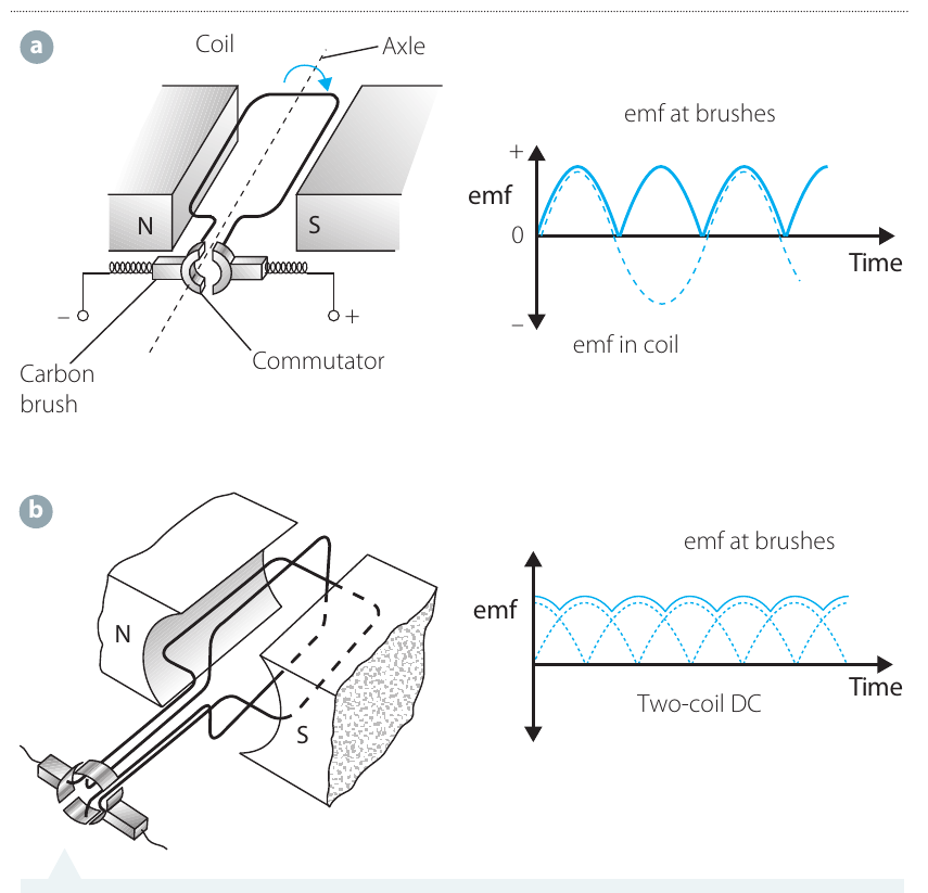
To produce smoother DC output:
- Multiple coils are used, offset at different angles (typically apart for two coils)
- Each coil has its own pair of commutator connections
- The combined output is much steadier, approaching a constant value
The two-coil configuration shown in the diagram produces a more consistent DC output, though some ripple remains. Real DC generators often use many coils to achieve very smooth output.
Safety Warning: Commutators can produce sparking across the insulating gaps, which poses a fire hazard near flammable gases (such as in car engines). This is one reason why AC induction motors are preferred in many applications - they have no commutator and therefore no spark risk.
AC induction motors
Structure and design
An AC induction motor operates using electromagnetic induction - no current is supplied directly to the rotating part. The key components are:
- Stator: Stationary electromagnets that create the magnetic field
- Rotor: The rotating component, typically a "squirrel cage" design
- Squirrel cage: Metal rods embedded lengthwise in a cylinder, connected at each end by conducting rings
Operating principle
The AC current in the stator coils creates an oscillating magnetic field. This time-varying field induces currents in the squirrel cage conductors (by Faraday's Law). The induced currents interact with the magnetic field to produce forces on the rotor bars.
Due to the symmetrical arrangement of the rotor bars, there is no net force on the rotor as a whole. However, each pair of opposite bars experiences a torque, and these torques add up to produce a net rotational torque that spins the rotor.
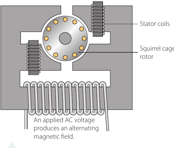
The relationship to transformers is useful: the stator acts as a primary coil creating a time-varying magnetic field, while the squirrel cage acts as a secondary coil where current is induced. However, unlike a transformer, the motor is designed to rotate, so the stator coils are arranged to produce a rotating magnetic field.
Speed characteristics
The AC mains supply in Australia has a frequency of Hz. This means:
- The current changes direction times per second
- An AC induction motor runs at approximately Hz without load
- This corresponds to about revolutions per minute (rpm)
- Under load, the rotor cannot quite keep pace with the rotating magnetic field, so actual speed is slightly less
Advantages and applications
AC induction motors are extremely common because they offer several advantages:
- Simple design: Fewer components than DC motors
- High efficiency: Minimal energy losses
- Low maintenance: No commutator or brushes to wear out
- Reliability: Robust construction with few failure points
Common applications include:
- Power tools (drills, circular saws)
- Kitchen appliances (blenders, food processors, microwaves)
- Industrial machinery
- Large-scale equipment
Most motors in household and industrial use are AC induction motors due to their practical benefits. The absence of a commutator means no sparking, making them safer in many environments and requiring virtually no maintenance over their lifetime.
Remember!
Key Points to Remember:
- Generators convert mechanical energy to electrical energy, while motors do the opposite
- AC generators produce sinusoidally varying EMF using slip rings:
- RMS values relate to peak values by dividing by : useful for AC power calculations
- DC generators use commutators to produce always-positive output; multiple coils smooth the result
- AC induction motors use electromagnetic induction (no direct current to rotor) with a squirrel cage design, offering simplicity, efficiency, and low maintenance