Electromagnetic Induction (HSC SSCE Physics): Revision Notes
Electromagnetic Induction
What is electromagnetic induction?
When the magnetic flux through an area changes over time, an electric field is created. This electric field produces what we call an induced EMF (electromotive force).
An EMF is the energy available per unit of electric charge. Despite its name containing the word "force", EMF is actually measured in volts (V) and represents energy per unit charge, not a force. EMF provides the energy needed for electric current to flow through a circuit.
Understanding EMF: Don't be confused by the name "electromotive force" - it's not actually a force! EMF measures energy per unit charge, just like voltage, which is why both are measured in volts (V).
An induced EMF is specifically one that is created by a changing magnetic flux. When a loop of wire is placed in a magnetic field and the flux through the loop changes, an EMF will be induced across the two ends of the loop. If the loop forms a complete circuit, this EMF will cause a current to flow.
The term potential difference refers to the difference in energy per unit charge between two points in an electric field. Potential difference is one example of an EMF, but as we'll see later, not all EMFs are potential differences.
Faraday's Law
Faraday's Law gives us a mathematical way to calculate the magnitude of the induced EMF when magnetic flux changes. The law states:
where:
- is the induced EMF in volts (V)
- is the final magnetic flux
- is the initial magnetic flux
- is the time interval
Unit conversion: The units T m² s⁻¹ are equivalent to volts (V). This makes sense because EMF is measured in volts!
Remembering that magnetic flux is , we can expand Faraday's Law:
Three ways to induce an EMF
Looking at the expanded formula, we can identify three ways to create an induced EMF:
Three Methods to Induce an EMF:
- Change the magnetic field strength,
- Change the area,
- Change the angle, , between the area and the magnetic field
Remember "Three B-A-θ changes" to recall these methods!
In practical applications, we usually change either the magnetic field or the angle:
- Changing the magnetic field: A coil connected to an alternating current (AC) produces a time-varying magnetic field. This principle is used in transformers and motors.
- Changing the angle: When a loop or coil of wire is placed in a magnetic field and spun, the angle changes continuously, inducing an EMF. The same effect occurs when spinning a magnet near a stationary loop. This principle is used in generators.
Simplifying for specific conditions
If we keep certain parameters constant, we can simplify the formula:
When area and angle are constant (only changes):
When field and area are constant (only changes):
Multiple loop coils
To generate a larger EMF, we can use a coil containing multiple loops of wire ( loops). Each loop has an EMF induced across its ends. Connecting loops in series is like connecting batteries in series - the total EMF is the sum of all individual EMFs:
More loops, more voltage: If you have loops, you get times the EMF! This is why coils with many turns are used in practical applications like transformers and generators.
Induced current
Once an EMF is induced, a current will flow if there are free charge carriers (like electrons in a metal wire) and a complete path for them to follow. The relationship between the induced EMF and the induced current follows Ohm's Law:
where is the current in amperes (A) and is the resistance in ohms (Ω).
Difference between EMF and potential difference
While EMF and potential difference both have the same units (volts) and both enable current to flow, they are fundamentally different:
Potential difference is the unique difference in potential energy per unit charge between two points in an electric field. If a charged particle moves from point A to point B in an electric field, its change in energy is regardless of the path taken. This is called a path-independent or conservative quantity.
Induced EMF between any two points in a changing magnetic field does not have a unique value - it depends on the path between the two points. This is because the EMF depends on the magnetic flux enclosed by the path. Different closed paths between two points may contain different amounts of flux, giving different EMFs. This makes induced EMF a path-dependent or non-conservative quantity.
Key Distinction:
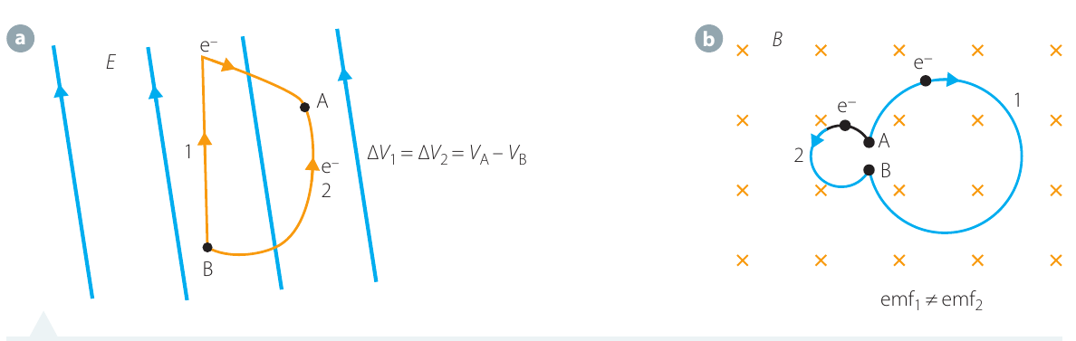
The diagram above illustrates the crucial difference between conservative and non-conservative fields:
-
Left (a): An electron moving between points A and B in an electric field has the same change in potential energy regardless of which path it takes () - this is path-independent.
-
Right (b): An electron passing through two different loops in a changing magnetic field experiences different EMFs because the loops enclose different amounts of magnetic flux () - this is path-dependent.
Remember: Potential difference is a type of EMF, but not all EMFs are potential differences.
Worked example: calculating induced EMF and current
Worked Example: Calculating Induced EMF and Current
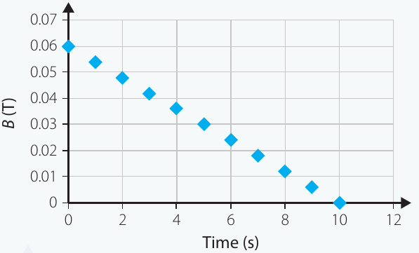
Problem: A wire loop with cross-sectional area is placed in a magnetic field. The loop is perpendicular to the field (). The magnetic field changes with time as shown in the graph below. The loop has a resistance of .
Find:
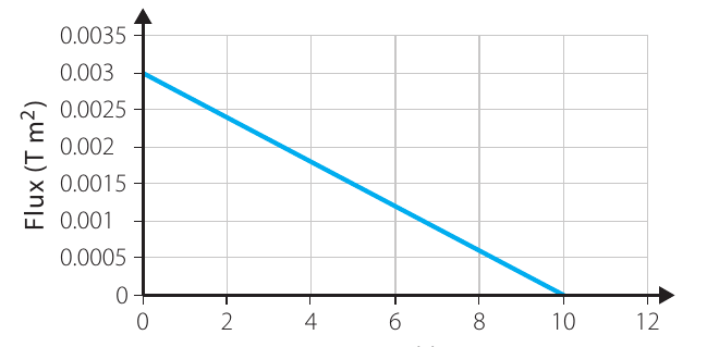
- (a) A graph of flux through the loop versus time
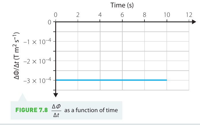
- (b) A graph of the rate of change of flux versus time
- (c) The EMF induced between the ends of the wire loop
- (d) The current induced in the loop
Given data:
Part (a): Flux versus time
Since , we have , so the flux formula simplifies to:
Using the values of from the graph and the given area, we can calculate flux at each time point and plot:
Part (b): Rate of change of flux
The rate of change of flux is the gradient (slope) of the flux-time graph from part (a). Since the graph is a straight line, the gradient is constant.
To find the gradient, we use rise over run:
Part (c): Induced EMF
Using Faraday's Law:
Substituting the value we calculated:
Part (d): Induced current
Using Ohm's Law to relate EMF to current:
Substituting values:
Exam tip: Always state your final answers with correct units and appropriate significant figures. Show your working clearly, including the formulas you use and the values you substitute.
Investigation 7.1: Electromagnetic induction
Aim
To investigate the current produced in a coil by a changing magnetic field.
Students should write their own inquiry question or hypothesis for this investigation.
Materials
- Strong bar magnet
- Coil of wire
- Sensitive ammeter or centre-zero galvanometer
Risk assessment
Magnets can break or become demagnetised when dropped, so be careful while handling them.
Safety First: Consider any additional risks specific to your investigation and how you will manage them to stay safe. Always follow proper laboratory safety procedures.
Method
Reading the ammeter: It may be difficult to read the exact magnitude of the current because the ammeter needle can swing quickly. You may simply need to note whether the current is 'large' or 'small'.
- Connect the coil to the ammeter.
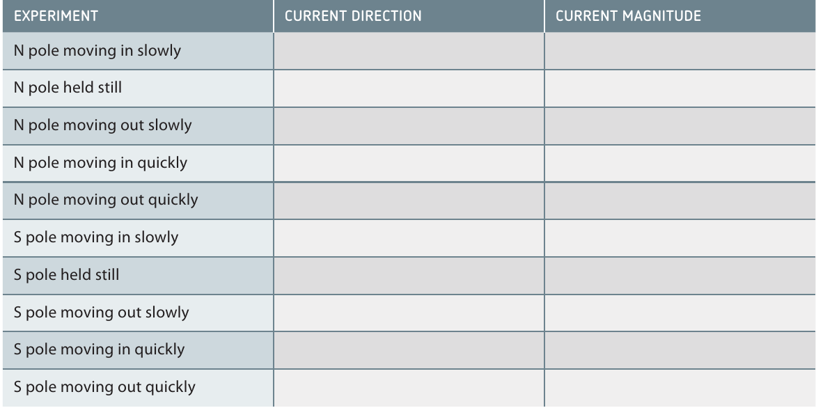
- Slowly move the north pole of the magnet into one end of the coil and observe what happens to the ammeter or galvanometer.
- Hold the north pole stationary within the coil and observe the ammeter or galvanometer.
- Slowly pull the magnet out again. Record what happens to the ammeter or galvanometer - note both the magnitude and direction of the current.
- Quickly move the north pole of the magnet into one end of the coil. Note what happens to the ammeter or galvanometer. Pull it out again quickly and observe again.
- Predict what you will see if you put the south pole of the magnet into the coil instead. Write down your prediction before testing it. Then repeat steps 2-5 with the south pole.
Results
Record your observations for each step in a table like the one below. Note both the direction and approximate magnitude of the current.
Analysis of results
- Sketch a graph of current versus time as the magnet was moved in and out of the coil. Label what was happening with the magnet along the time axis.
- Draw a diagram showing the magnetic field lines of the bar magnet.
- Relate the direction of the current to the changing magnetic flux through the coil.
Discussion
- How is the magnitude of the current related to the speed of the magnet?
- How does the direction of current vary with the changing magnetic flux?
- Give the answer to your inquiry question or state whether your hypothesis was supported.
Conclusion
Write a conclusion summarising the outcomes of your investigation. Your conclusion should reference your data and clearly answer the aim of the investigation.
Lenz's Law
The negative sign in Faraday's Law () is not just mathematical - it tells us something important about the direction of the induced current.
Lenz's Law states: An induced EMF acts to produce an induced current in the direction that causes a magnetic flux that opposes the change in flux that induced the EMF.
In simpler terms: the induced current flows in whichever direction creates a magnetic field that opposes the change that caused it.
Why does this happen?
Conservation of Energy Connection
Lenz's Law is fundamentally a consequence of the conservation of energy.
When magnetic flux through a loop changes, the potential energy of the changing magnetic field is transformed into electric potential energy. This creates an electric field that does work on free electrons in the wire, causing them to flow and creating the induced current. The induced current draws its energy from the changing magnetic flux (via the electric field), which reduces the rate at which the flux changes.
Consider what would happen if the current flowed in the opposite direction, producing an increase in the magnetic flux through the loop. The flux would increase more, inducing an even bigger current, which would increase the flux even more, and so on. This would create a 'perpetual motion machine' generating more and more current without any energy source - violating the conservation of energy. This cannot happen, so the current must flow in the direction that opposes the flux change.
Lenz's Law in action
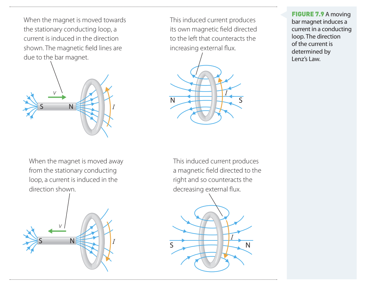
The diagrams above show how Lenz's Law determines current direction:
When a magnet approaches a coil:
- The flux through the loop is increasing
- The induced current flows in a direction that creates a magnetic field opposing this increase
- The induced field points away from the approaching magnet, effectively trying to push it away
When a magnet moves away from a coil:
- The flux through the loop is decreasing
- The induced current flows in a direction that creates a magnetic field opposing this decrease
- The induced field points toward the departing magnet, effectively trying to pull it back
Lenz opposes change: In both cases, the induced magnetic field acts to resist the motion causing the flux change. Remember: the induced effect always opposes what caused it!
Eddy currents
Induced currents don't only occur in wire loops - they can form in any material containing free charge carriers (such as metals).
When a magnet is moved near a piece of metal, the changing magnetic field induces an EMF in the metal. This EMF causes electrons to flow in circular patterns, forming loops and spirals of current similar to eddies in water when you stir it. These are called eddy currents.
Effects of eddy currents
Magnetic braking: According to Lenz's Law, these eddy currents create their own magnetic fields that oppose the changing flux from the moving magnet. These induced magnetic fields act to slow down or brake the moving magnet. This principle is used in magnetic braking systems.
Heating: The eddy currents flowing through the metal encounter electrical resistance, which converts some of their energy into heat. This is why metals can warm up when exposed to rapidly changing magnetic fields.
Applications of Eddy Currents
Eddy currents are both useful and problematic:
- Useful applications: Induction heating, magnetic braking, metal detectors
- Unwanted effects: Energy losses in transformers and motors due to heating
Understanding electromagnetic induction allows engineers to either harness or minimize eddy currents depending on the application.
Remember!
Key Points to Remember:
-
EMF is energy per unit charge measured in volts (V), providing the energy needed for current to flow
-
Induced EMF is created when magnetic flux through an area changes with time
-
Faraday's Law: - the induced EMF equals the negative rate of change of magnetic flux
-
Three ways to induce EMF: change the magnetic field (), change the area (), or change the angle () - remember "Three B-A-θ changes"!
-
Multiple loops multiply EMF: loops in series produce times the EMF of a single loop
-
Path dependence matters: Potential difference is path-independent (conservative), but induced EMF is path-dependent (non-conservative)
-
Lenz's Law: Induced current always flows in the direction that opposes the flux change that created it - this is conservation of energy in action. Remember: "Lenz opposes change"!
-
The negative sign in Faraday's Law represents Lenz's Law - it tells us the induced effect opposes the change
-
Eddy currents are circular currents induced in bulk conductors, creating opposing magnetic fields and causing heating
-
Faster change, bigger EMF: The rate of flux change determines the magnitude of the induced EMF