Transformers (HSC SSCE Physics): Revision Notes
Transformers
Introduction to transformers
Transformers are electromagnetic devices that use induction to convert alternating current (AC) voltages from one level to another. They work by using a changing magnetic field in one coil (the primary coil) to induce a voltage and current in a second coil (the secondary coil). The two coils are not electrically connected—they are linked only through the magnetic field.
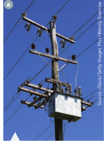
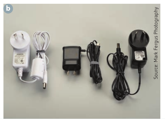
Transformers are found in many applications, from small plug packs that charge mobile phones to large industrial units at power stations and electricity substations. They can be used to increase voltage (step-up transformers) or decrease voltage (step-down transformers).
Transformers only work with alternating current (AC), not direct current (DC). This is because a changing magnetic field is required to induce an emf in the secondary coil. With DC, the magnetic field is constant, so no emf is induced.
Alternating current (AC)
What is alternating current?
Alternating current is an electric current that periodically reverses its direction of flow. Unlike direct current (DC), which flows steadily in one direction, AC oscillates back and forth in a sinusoidal pattern.
Describing AC signals
AC currents and voltages vary sinusoidally with time, creating a wave pattern that can be described using several key parameters:
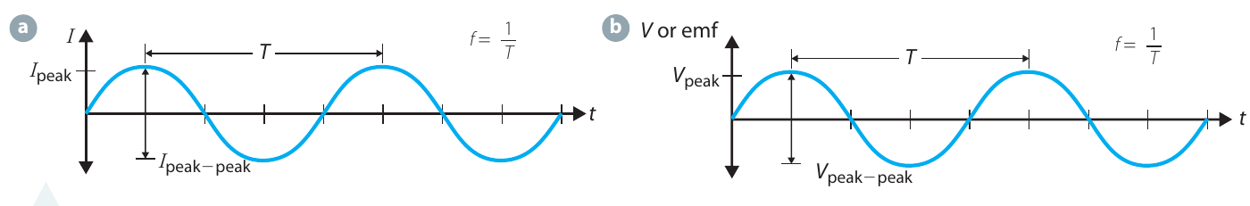
Amplitude measurements:
- Peak current (): The maximum current value reached during the cycle
- Peak-to-peak current (): The total variation from maximum positive to maximum negative current; equal to
- Peak voltage (): The maximum voltage (emf) value
- Peak-to-peak voltage (): The total voltage variation; equal to
Time variation:
- Period (): The time taken for one complete cycle (measured in seconds)
- Frequency (): The number of cycles per second (measured in hertz, Hz)
The relationship between period and frequency is:
Root mean square (RMS) values
Although AC voltage and current oscillate between positive and negative values, they still deliver power to circuits. To quantify this, we use RMS (root mean square) values. The RMS value represents the equivalent DC voltage or current that would deliver the same power.
The process for calculating RMS values involves three steps:
- Square the AC signal to make all values positive
- Average (find the mean of) the squared values
- Square root the average to get the RMS value
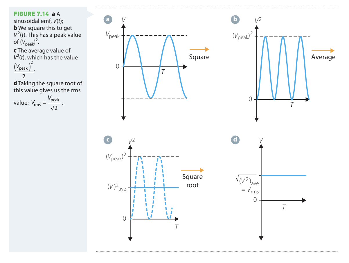
Mathematically, this gives:
AC systems are usually described using RMS values. For example, Australian mains power is specified as 230V RMS, not peak voltage.
Worked Example: Converting RMS to peak voltage
Question: The mains supply in Australia provides an AC potential difference of 230V RMS. To what peak value of potential difference does this correspond?
Solution:
| Step | Working |
|---|---|
| Given data | |
| Relationship | |
| Rearrange | |
| Substitute | |
| Calculate | |
| Answer | (2 significant figures) |
Australian mains power supply
The standard household electricity supply in Australia delivers 230V RMS between the active and neutral terminals. This is an AC supply that oscillates sinusoidally at a frequency of 50 Hz.
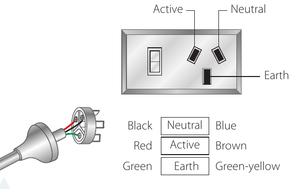
Australian power sockets have three connections:
- Active (Live): Brown or red wire; carries the alternating voltage
- Neutral: Blue or black wire; completes the circuit
- Earth (Ground): Green or green-yellow wire; safety connection at 0V
Historical note: Until the 1980s, Australian mains power was standardised at 240V RMS. It was changed to 230V RMS to align with international standards.
Structure and operation of transformers
Flux linkage
Transformers work through electromagnetic induction via flux linkage—the magnetic flux from one coil passes through the other coil. There is no direct electrical connection between the primary and secondary coils.
Two methods achieve flux linkage:
- Coaxial coils: One coil placed inside the other (used in some cordless appliances like kettles)
- Ferromagnetic core: The more common method, using an iron core to link the coils
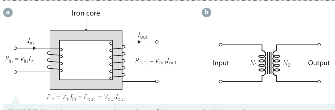
How ferromagnetic cores work
In a core-linked transformer, the following process occurs:
- The primary coil wraps around one part of a ferromagnetic (usually iron) core
- The secondary coil wraps around another part of the same core
- AC current in the primary coil creates a time-varying magnetic field
- This magnetises the entire iron core, not just the part inside the primary coil
- The magnetised core creates a time-varying magnetic field in the secondary coil
- The changing field in the secondary coil induces an emf (by Faraday's Law)
- This emf drives a current in the secondary coil
The result is that an AC current in the primary coil induces an AC current in the secondary coil with the same frequency but potentially different amplitude.
Transformer equations
Deriving the relationships
For an ideal transformer with perfect flux linkage, the rate of flux change () is the same through both coils. Using Faraday's Law:
For the primary coil:
For the secondary coil:
Where and are the number of turns in the primary and secondary coils respectively.
Since is the same for both:
For an ideal transformer (100% efficient), power in equals power out:
This gives:
The transformer equations
Combining these relationships gives the transformer equations:
These can be rearranged to find specific values:
- Secondary voltage:
- Secondary current:
Important exam tip: Notice that the voltage ratio has on top, but the current ratio has on top (they are inverted).
Worked Example: Finding turns and voltage ratios
Question: A transformer has a primary coil with 10,000 turns. An AC current of 5.0A flowing in the primary coil induces a current of 1.0A in the secondary coil.
a) What is the number of turns in the secondary coil?
b) What is the ratio of the potential differences across the secondary and primary coils?
Solution:
| Part | Step | Working |
|---|---|---|
| Given | Data | , , |
| a | Current-turns relationship | |
| Rearrange | ||
| Substitute | ||
| Answer | turns | |
| b | Voltage ratio | |
| Substitute | ||
| Answer | The secondary voltage is 5 times the primary voltage |
Step-up and step-down transformers
Step-up transformers
A step-up transformer increases the voltage from primary to secondary. This occurs when the secondary coil has more turns than the primary coil ().
From the transformer equations:
If , then (output voltage is greater than input voltage).
However, energy is conserved. The increased voltage comes at the cost of decreased current:
If , then (output current is less than input current).
Applications:
- Converting 12V car alternator output to 230V for appliances
- Increasing generator output voltage at power stations for long-distance transmission
Step-down transformers
A step-down transformer decreases the voltage from primary to secondary. This occurs when the secondary coil has fewer turns than the primary coil ().
If , then (output voltage is less than input voltage).
And: (output current is greater than input current).
Applications:
- Phone chargers (converting 230V to 5-12V)
- Laptop power supplies
- Electricity substations (reducing transmission voltages to 230V for households)
- Regional power distribution (reducing high-voltage lines to household supply)
Worked Example: Step-down transformer calculation
Question: A step-down transformer supplies 230V to a house. The house is drawing 15A to run various appliances. If the input voltage to the transformer is 10kV, what current is flowing in the primary coil?
Solution:
| Step | Working |
|---|---|
| Given data | , , |
| Relationship | |
| Rearrange | |
| Substitute | |
| Calculate | |
| Answer | (2 significant figures) |
Electricity distribution in Australia
Transformers play a crucial role in electricity distribution networks. The journey of electricity from power station to home involves both step-up and step-down transformers:
- Power station: Generators produce electricity at relatively low voltage
- Step-up transformer: Increases voltage to around 100kV or more for transmission
- Transmission lines: High voltage reduces current, minimising energy loss in long-distance lines
- Substation: Step-down transformers reduce voltage for distribution
- Distribution lines: May carry high voltage (around 8-50kV) for longer distances or lower voltage (230V) for local supply
- Local transformers: In regional areas, pole-mounted transformers reduce high voltage to 230V for individual houses
- Household supply: 230V RMS delivered to homes and businesses
Why use high voltages for transmission?
Higher transmission voltages result in lower currents (for the same power). Since power loss in transmission lines is proportional to current squared (), lower currents mean significantly reduced energy losses.
Real transformers and energy losses
The transformer equations assume ideal conditions: perfect flux linkage and 100% efficiency. Real transformers deviate from these assumptions, losing energy in several ways:
Imperfect flux linkage
Not all magnetic flux from the primary coil passes through the secondary coil. Some "stray field" extends beyond the core and can:
- Induce eddy currents in nearby materials (transformer case, supports)
- Cause heating in these materials
- Create vibrations, producing the characteristic buzzing sound near large transformers
Resistive heating in coils
The wire in transformer coils has resistance. When current flows, energy is dissipated as heat according to Ohm's Law. This is why phone chargers and other transformers become warm during use.
Reducing this loss: Use thicker wires with lower resistance.
Eddy currents in the core
The changing magnetic field induces eddy currents within the ferromagnetic core itself. By Lenz's Law, these currents oppose the flux changes, wasting energy as heat.
Reducing this loss: Use a laminated core consisting of thin layers of ferromagnetic material separated by insulating material. This restricts the paths available for eddy currents, reducing their magnitude.
Magnetisation losses
Each time the AC current reverses direction, the core must be magnetised in the opposite direction. This repeated magnetisation and demagnetisation process consumes energy, appearing as heat in the core.
Reducing this loss: Develop more efficient magnetic materials that can be magnetised and demagnetised with less energy loss.
Modern transformers are typically 95-99% efficient, with the lost energy appearing primarily as heat. Large transformers may require cooling systems to dissipate this heat.
Investigation: Transformers
Aims
This investigation explores how changing magnetic flux in a transformer's secondary coil is produced by varying the voltage across the primary coil. It also verifies the relationship between voltage ratios and turns ratios for both step-up and step-down transformers.
Safety considerations
| Risk | Management Strategy |
|---|---|
| Power supplies can cause electric shocks | Limit voltages to maximum 12V. Ensure all equipment is checked by teacher before use |
Apparatus
- 2 air-core solenoids with known number of turns
- Iron rod (ferromagnetic core)
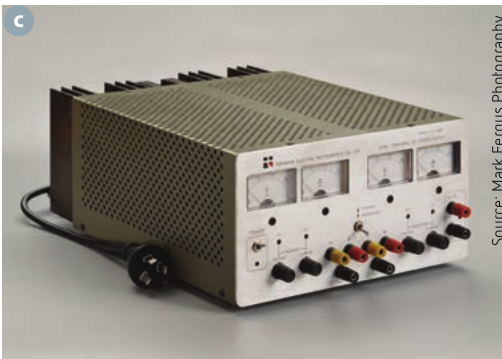
- Variable AC/DC power supply or separate AC and DC supplies
- Connecting leads
- Cathode ray oscilloscope (CRO)
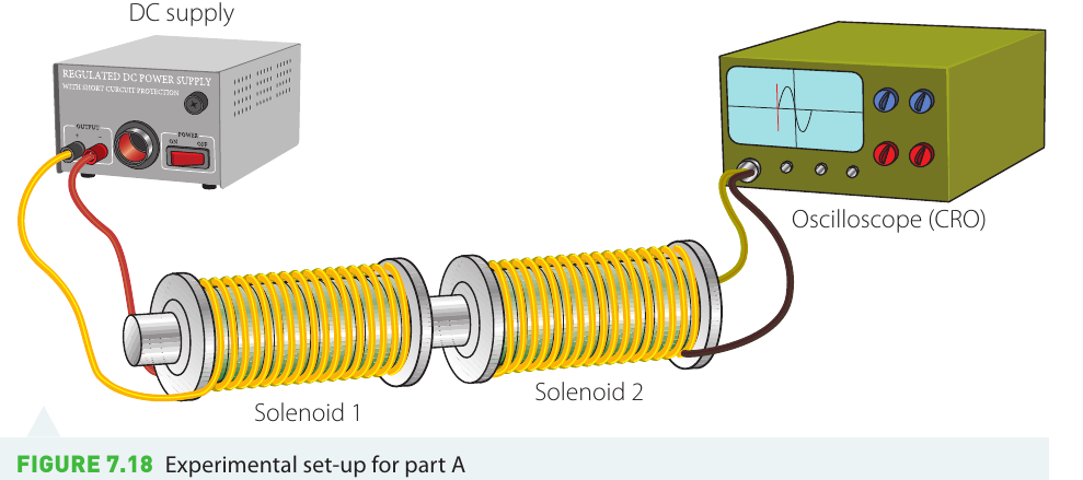
Experimental setup
Method overview
Part A: Investigates the difference between DC and AC in electromagnetic induction
- Connect solenoids end-to-end with iron rod through centres
- Apply DC voltage to primary solenoid
- Observe oscilloscope trace when switching DC on/off
- Compare with constant DC
Part B: Investigates the transformer voltage relationship
- Replace DC with AC supply
- Measure output voltage for different input voltages
- Swap primary and secondary coils
- Compare experimental results with theoretical predictions
Analysis
The investigation involves:
- Converting peak voltage measurements to RMS values
- Calculating expected RMS output using transformer equations
- Comparing experimental and theoretical results
- Explaining discrepancies based on non-ideal behaviour
Key finding: An emf is induced in the secondary coil only when the magnetic flux is changing. This occurs continuously with AC but only during switching transients with DC.
Key Points to Remember:
- Transformers change AC voltages using electromagnetic induction between two magnetically linked coils with no electrical connection
- AC current varies sinusoidally with time, described by peak values (, ) and RMS values (, )
- Australian mains supply is 230V RMS at 50Hz, with peak voltage of approximately 325V
- Transformer equations relate voltages, currents and turns:
- Step-up transformers () increase voltage but decrease current; used at power stations for transmission
- Step-down transformers () decrease voltage but increase current; used in chargers and at substations
- Real transformers lose energy as heat through resistive heating, eddy currents and magnetisation; laminated cores improve efficiency by reducing eddy currents