Current-Carrying Wires in Magnetic Fields (HSC SSCE Physics): Revision Notes
Current-Carrying Wires in Magnetic Fields
What is the motor effect?
When a wire carrying an electric current is placed in a magnetic field, it experiences a force. This phenomenon is called the motor effect. The motor effect is fundamental to how electric motors work, which is why it has this name.
The motor effect occurs because the moving charged particles (usually electrons) within the wire experience a magnetic force. Since these particles are constrained to move only within the conductor, they transfer this force to the wire itself, causing the entire wire to move. This is the basic principle that allows us to convert electrical potential energy into kinetic energy in devices ranging from the tiny vibrating motor in your mobile phone to massive industrial motors and even advanced weapons systems like rail guns.
The motor effect is a practical demonstration of how electromagnetic forces can do mechanical work. This principle is used in countless devices we rely on every day, from electric cars to computer hard drives to power tools.
Why current-carrying wires experience forces
To understand the motor effect, we need to consider what happens at the microscopic level inside a current-carrying wire. Electric current consists of moving charged particles, typically electrons in a metal conductor. Each of these moving electrons experiences a force when it moves through a magnetic field, given by the equation:
where is the charge, is the velocity of the particle, is the magnetic field strength, and is the angle between the velocity and the magnetic field.
The key point is that electrons in a conductor cannot escape from the wire. The resistance of the surrounding insulation or air is much higher than the resistance of the metal wire, so electrons are constrained to flow only within the conductor. When the electrons experience a magnetic force, they push against the structure of the wire and pull it along in the direction of the force.
Consider a section of wire with length , carrying current , as shown below:
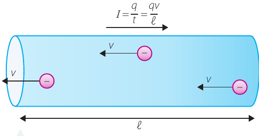
The electrons move through the wire with an average speed , in the opposite direction to the conventional current . Remember that conventional current is defined as the direction that positive charges would move, which is opposite to the actual electron flow.
We can relate the current to the electron motion using these fundamental relationships:
where current is measured in amperes (A), and 1 A = 1 C s.
The average speed of electrons is:
where is the time it takes electrons to travel through the displacement along the wire.
Deriving the force equation
We can now derive an expression for the total force on a section of wire by starting with the force on the individual moving electrons. The force on the electrons is:
Substituting :
Rearranging:
Since , we can substitute to get:
This can also be written as:
where represents the component of the magnetic field perpendicular to the wire.
Key equation: The force experienced by a current-carrying wire in a magnetic field is:
where:
- is the force in newtons (N)
- is the length of wire in the magnetic field in metres (m)
- is the current in amperes (A)
- is the magnetic field strength in tesla (T)
- is the angle between the current direction and the magnetic field
Note that even though it's electrons (negative charges) carrying the current, we don't need to introduce a negative sign when we replace with . This is because we define current as the direction that positive charges would flow, which is already opposite to the electron motion.
Worked Example: Overhead Power Line
Question: An overhead power line carrying a current of A is in a magnetic field of T due to Earth's magnetic field. The field is perpendicular to the wire. What force per unit length does the wire experience?
Solution:
Given data:
- A
- T
- (perpendicular)
We need to find the force per unit length, .
Starting with the force equation:
Rearranging for force per unit length:
Substituting values:
Checking units: 1 A T = 1 C s × 1 kg s C = 1 kg s = 1 N m
Answer: N m
This is quite a large force considering the length of high-voltage power lines. However, power lines carry alternating current that reverses direction 50 times per second, so the force also alternates direction rather than constantly pulling the wire in one direction.
How the angle affects the force
The magnitude of the force depends critically on the angle between the current and the magnetic field:
- When parallel (): , so . There is no force when the current and field are in the same direction.
- When perpendicular (): , so . This is the maximum possible force.
- At intermediate angles: The force is , which is between zero and the maximum.
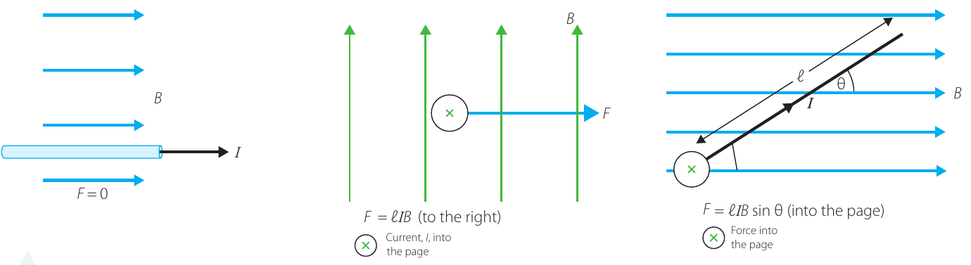
Exam tip: Always check whether the field and current are perpendicular. If they are, you can use the simpler formula . If not, you must include .
Direction of the force
The equation gives us the magnitude of the force, but force is a vector quantity - it has both magnitude and direction. The direction of the force is always perpendicular to both the magnetic field and the direction of the current.
The right-hand rule
We use the right-hand rule to determine the direction of the force:
- Hold the fingers of your right hand together and point your thumb straight out at a right angle
- Point your fingers in the direction of the current ()
- Curl your fingers towards the direction of the magnetic field ()
- Your thumb now points in the direction of the force ()
Important: Always use your right hand, never your left!
Alternative method: Point your index finger along the current direction, then point your middle finger towards the field. Your thumb will point in the direction of the force.
Worked Example: Determining Force Direction
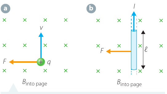
Question: A magnetic field is pointing into the page and a current-carrying wire is in the plane of the page carrying current to the right. What is the direction of the force on the wire?
Solution:
First, draw a diagram showing the field and current. The magnetic field into the page is represented by × symbols.
Using the right-hand rule:
- Point your fingers to the right (direction of current)
- Curl them forwards, away from you (into the page, direction of field)
- Your thumb points upward
Therefore, the force is directed up the page.
Answer: (upward)
The definition of magnetic field
The force equation for current-carrying wires allows us to give a formal mathematical definition of magnetic field strength. Up to this point, we've discussed what magnetic fields do, but we haven't precisely defined how to measure them.
Magnetic field is defined as the magnetic force per unit current, per unit length, on a current-carrying wire in a magnetic field.
Mathematically:
where:
- is measured in tesla (T)
- is the force in newtons (N)
- is the current in amperes (A)
- is the length in metres (m)
- is the angle between the current and the field
This definition is consistent with how we define other fields:
- Gravitational field is force per unit mass
- Electric field is force per unit charge
- Magnetic field is force per unit current per unit length
This consistency shows the deep connection between different types of fields in physics.
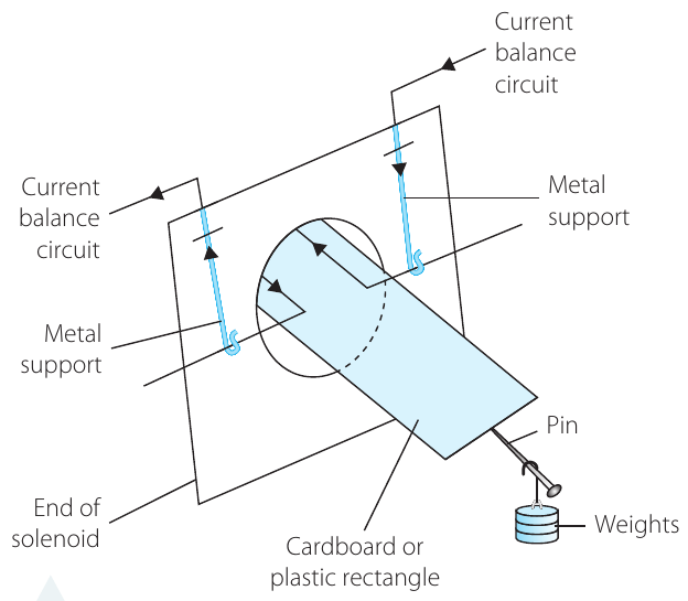
Investigation: Measuring magnetic force with a current balance
A current balance is an experimental apparatus that allows us to measure the magnetic force on a current-carrying wire and thereby determine the strength of a magnetic field. The device works like a see-saw, balancing the magnetic force against a known gravitational force.
Aim
To measure the magnetic force on a current balance to find the magnetic field strength in a solenoid.
Apparatus
Part A - Building the current balance:
- Air-core solenoid
- Thin, stiff, lightweight insulator (cardboard or plastic)
- Stiff conducting wire
- Copper or zinc sheet
- Pin
- Fine sandpaper
- Scissors and tin snips
- Short pieces of wire of known mass (for weights)
- 2 DC power supplies
- 2 ammeters (0-5 A)
- 2 variable resistors or rheostats
- 2 switches
- Alligator clips and connecting leads
Risk assessment
| What are the risks? | How can you manage these risks? |
|---|---|
| Electricity can shock and cause damage to equipment | Use low voltages and currents only |
| Scissors can cut skin and have sharp tips | Be very careful when using scissors. Do not run with scissors |
Method
Part A - Construction:
- Cut a rectangle from the insulator so that half will fit into the solenoid and half extends outside.
- Attach a small pin to the middle of one short side of the rectangle, overhanging the end that will sit outside the solenoid. This pin will act as the pivot point.
- Make a rectangular half-loop of conducting wire to sit near the edges of the insulating rectangle that goes into the solenoid. Attach this firmly to the insulator.
- Cut two metal supports from the metal sheet, bend them, and attach them to the end of the solenoid. These supports must connect to the current balance circuit but must not make electrical contact with the solenoid itself.
- Bend the ends of the rectangular half-loop so they rest on the metal supports, completing the electrical circuit.
- Use sandpaper to clean all metal surfaces to ensure good electrical contact.
- Measure the length of the current element that is perpendicular to the magnetic field. Remember that the magnetic field inside a solenoid runs parallel to its long axis, so the perpendicular section is the part of the wire loop that crosses the solenoid.
- Balance the current balance by hanging pieces of wire or small weights over the pin.
Part B - Taking measurements:
- Connect the balance and solenoid circuits as shown in the diagram below.
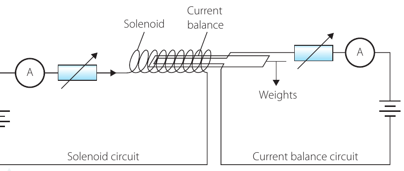
- Close the switch in the solenoid circuit and adjust the current to 2.5-3.5 A.
- Close both switches and observe the current balance. The inner end should be pushed down by the magnetic force. If not, adjust the solenoid circuit.
- Adjust the number of weights and their positions until the current balance is balanced (horizontal).
The key to this experiment is achieving a precise balance. Take your time adjusting the weights and their positions to get the current balance perfectly horizontal before taking readings.
Results
Record the following measurements in a table:
- Current in solenoid
- Current in current element
- Distance from pivot to current element
- Distance from pivot to balancing weights
Include units for all measurements.
Analysis
Calculate and add to your table:
- Masses of weights used
- Gravitational force on balancing masses:
- Torque due to gravitational force:
- Magnetic force on current element (from torque balance)
- Magnetic field in solenoid
The key principle is that when balanced:
Therefore:
Once you know the magnetic force, you can calculate the magnetic field using:
(assuming the field is perpendicular to the current, so )
The theoretical magnetic field inside a solenoid is given by:
where:
- T m A (permeability of free space)
- is the number of turns in the solenoid
- is the solenoid current (A)
- is the length of the solenoid (m)
Compare your experimental value with this theoretical prediction.
Applications of the motor effect
The motor effect has numerous practical applications in modern technology. Here we examine two important examples that demonstrate how electromagnetic forces can be harnessed for useful purposes.
Loudspeakers
A loudspeaker is essentially a linear motor that converts electrical signals into sound waves. When sound is converted to an electrical signal (such as in a microphone or from a digital source), the current oscillates at the same frequency as the original sound.
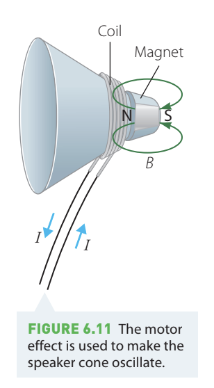
How a speaker works:
- The oscillating current flows through a coil of wire wrapped around a cone
- This coil sits in front of a large permanent magnet
- The motor effect creates a force on the current-carrying coil
- As the current alternates, the coil is alternately attracted to and repelled by the magnet
- This makes the speaker cone oscillate back and forth
- The oscillating cone creates sound waves in the air at the same frequency as the electrical signal
The motor effect therefore allows us to faithfully reproduce sounds by converting electrical variations into mechanical vibrations.
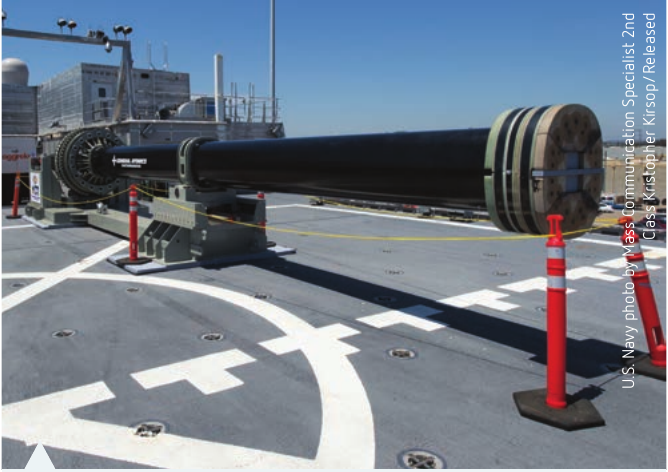
Rail guns
A rail gun is an advanced electromagnetic weapon that uses the motor effect to fire a projectile at extremely high speeds without using any explosive propellant.
In a rail gun:
- A conducting projectile sits across two conductive rails
- A very large current flows through the rails and through the projectile
- The currents in the rails themselves produce a strong magnetic field
- This magnetic field exerts a force on the current flowing through the projectile
- The projectile is accelerated along the rails to very high speeds
Rail guns require enormous currents but offer several advantages over conventional guns: no explosive chemicals, higher projectile velocities, and greater range. They are currently being developed for military applications.
Remember!
Key Points to Remember:
- Current-carrying wires experience a force in a magnetic field because the moving electrons in the wire experience a magnetic force, which is transferred to the wire
- The force is given by:
- The force is maximum () when the current and field are perpendicular ()
- The force is zero when the current and field are parallel ()
- Use the right-hand rule to find the direction: point fingers along current, curl towards field, thumb shows force direction
- Magnetic field is defined as: (force per unit current per unit length)
- The motor effect is used in many applications including electric motors, loudspeakers, and rail guns