Forces on Parallel Current-Carrying Wires (HSC SSCE Physics): Revision Notes
Forces on Parallel Current-Carrying Wires
Introduction
When electric current flows through a wire, two important electromagnetic phenomena occur. First, the wire generates a magnetic field in the surrounding space. Second, if the wire is placed in an external magnetic field, it experiences a force. These two effects work together to create an interaction between current-carrying wires.
A current-carrying wire has a dual role in electromagnetism: it both creates its own magnetic field and responds to external magnetic fields by experiencing forces.
When two wires carrying current are positioned parallel to each other, they interact magnetically. Each wire produces its own magnetic field, and this field exerts a force on the other wire. The result is that the two wires either attract or repel each other, depending on the direction of the currents.
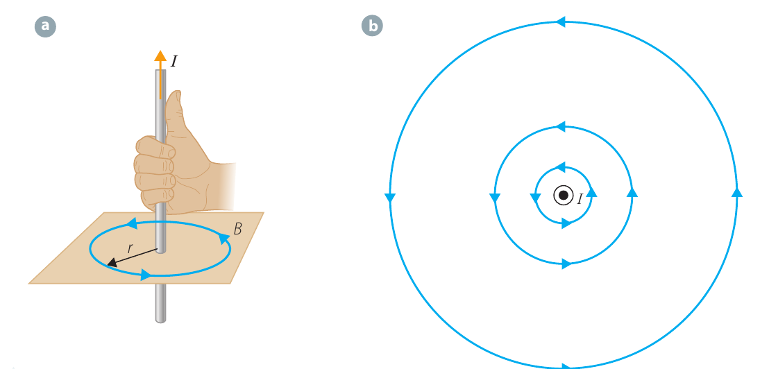
Magnetic field around a current-carrying wire
A long, straight wire carrying current creates a magnetic field in the space around it. The strength of this field depends on the current and the distance from the wire:
Where:
- = magnetic field strength (in tesla, T)
- = permeability of free space = T m A⁻¹
- = current flowing through the wire (in amperes, A)
- = distance from the wire (in metres, m)
The magnetic field forms concentric circular loops centred on the wire. To find the direction of these field lines, we use the right-hand rule: point your right thumb in the direction of the current, then curl your fingers around the wire. Your fingers indicate the direction of the magnetic field lines.
Right-hand rule for magnetic field direction: Point your right thumb along the direction of current flow, then curl your fingers around the wire. The direction your fingers curl shows the direction of the magnetic field lines.
Force between parallel current-carrying wires
Basic principle
When two parallel wires carry current, each wire sits within the magnetic field created by the other wire. Since a current-carrying wire in a magnetic field experiences a force, each wire exerts a force on the other.
The force on a current-carrying wire in a magnetic field is given by:
Where is the component of current perpendicular to the magnetic field.
Deriving the force equation
Consider two parallel wires separated by distance . Wire 1 carries current and wire 2 carries current .
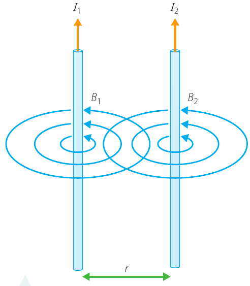
Derivation approach: We'll find the force in three steps: first calculate the magnetic field from wire 1, then find the force this field exerts on wire 2, and finally substitute to get the complete equation.
Step 1: Calculate the magnetic field created by wire 1 at the position of wire 2.
Using the equation for the magnetic field around a wire:
Step 2: Determine the force on wire 2 due to this magnetic field.
The force on wire 2 is:
Since the wires are parallel, the current is perpendicular to the magnetic field, so and .
Therefore:
Step 3: Substitute the expression for :
Where is the length of wire over which the two wires are parallel.
Direction of the force
The direction of the force depends on whether the currents flow in the same direction or in opposite directions.
Same direction currents - attractive force
When both currents flow in the same direction, the forces are attractive. The wires pull towards each other.
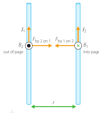
Using the right-hand rule:
- Wire 1 creates a magnetic field that points into the page at the position of wire 2
- Applying the right-hand rule to the current in field gives a force pointing towards wire 1
- Similarly, wire 2 creates a field pointing out of the page at wire 1
- The force on wire 1 points towards wire 2
Opposite direction currents - repulsive force
When the currents flow in opposite directions, the forces are repulsive. The wires push away from each other.
Using the right-hand rule again shows that both forces point away from the other wire, causing repulsion.
Remember the direction rule:
- Currents in the same direction → wires attract
- Currents in opposite directions → wires repel
Memory aid: "SAFE" - Same direction = Attractive Force Effect
Investigation: Observing forces on parallel current-carrying wires
This investigation demonstrates the forces between parallel current-carrying wires experimentally.
Aim
To observe the effects of the force that one current-carrying wire exerts on a second parallel current-carrying wire.
Materials
- High current DC power supply (such as a 12 V battery)
- Heavy duty rheostat, 0–10 Ω
- Heavy duty wires with alligator clips
- Heavy duty momentary switch
- Two lengths of flexible cable, approximately 50 cm long
- Vertical board with movable insulated pegs
- Paper with grid markings
- Camera or video camera
- Tripod
Risk assessment
| Risk | Safety measures |
|---|---|
| Large currents can cause electric shock and damage equipment | Only perform as a teacher demonstration |
| Follow all instructions carefully | |
| Keep equipment disconnected when not in use | |
| Never have current flowing for more than one second |
Critical safety requirements:
- This investigation must only be conducted as a teacher demonstration
- If any sparking or smoke occurs, immediately turn off the switch and disconnect the circuit
- Always disconnect the power supply when not in use
- Never maintain current flow for more than one second
Method
Part A: Effect of varying current
- Attach the gridded paper to the board so the wires will hang in front of it. Grid markings should be at 1 cm or 0.5 cm intervals.
- Connect the parallel circuit shown below, but do not connect both battery terminals yet.
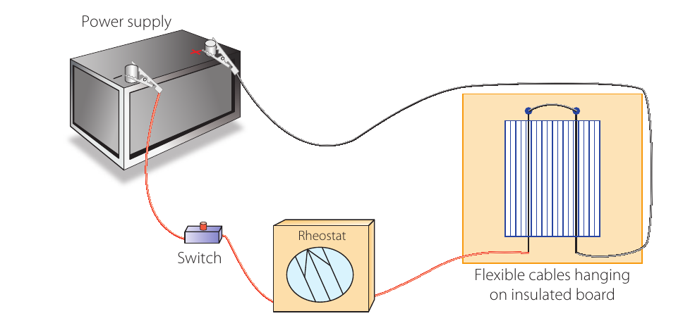
- Attach the flexible wires to the pegs so they hang straight down about 2 cm apart.
- Start with the rheostat adjusted to give maximum resistance.
- Take a reference photo showing how the wires hang against the grid with no current. Keep the camera position fixed (ideally on a tripod).
- Ensure the switch is off, then connect the battery terminals.
- One person turns the switch on for only one second or less. Another person photographs the wires while current flows.
- Adjust the rheostat to lower resistance.
- Repeat the photo process.
- Repeat at least twice more to build a series showing wire behaviour with increasing current. Do not reduce resistance below 1 Ω.
Part B: Effect of varying distance
- Keep the rheostat at a constant setting that produces clear wire deflection.
- Take photos as before.
- Increase the spacing between wires and observe the change in deflection.
- Repeat with at least one more distance setting.
Part C: Effect of varying current direction
- Disconnect the circuit and reconnect as a series circuit (currents in opposite directions).
- Repeat the experiment, taking photos of wire behaviour.
- Disconnect the circuit.
Results
Record your observations systematically:
- Measure wire deflection from photographs using the grid as a scale
- Record data in tables showing how deflection varies with current and distance
- Note whether wires were attracted or repelled in each configuration
Analysis
If you have sufficient data points, graph deflection against current and against distance. Even with limited data, you should observe:
- Whether deflection (and therefore force) increases or decreases with current
- Whether force increases or decreases with distance between wires
- Whether wires attract or repel when currents are in the same vs opposite directions
Use this information to draw force diagrams for wires in each circuit configuration.
Key observations to look for: The investigation should reveal that force increases with current, decreases with distance, and that the direction of force (attractive vs repulsive) depends on whether currents flow in the same or opposite directions.
Discussion questions
- Draw diagrams showing forces acting on each wire when currents flow in the same direction and when they flow in opposite directions.
- Describe the relationship between force on the wires and: (a) the current flowing, and (b) the distance between wires.
- State whether your hypothesis was supported.
Worked example: Calculating force between parallel wires
Worked Example: Force Between Parallel Wires
Question: Two parallel wires are spaced 5.0 cm apart. Each carries a current of 15 A, with currents flowing in opposite directions (one up, one down). Calculate the force per unit length that each wire exerts on the other. Give magnitude and direction.
Solution:
Step 1: Identify the given information.
- A
- m
Step 2: Use the force equation.
The force between parallel current-carrying wires is:
Step 3: Calculate force per unit length.
Rearranging for force per unit length:
Step 4: Substitute values.
Step 5: Calculate the result.
Step 6: Check units.
Therefore:
Step 7: Determine the direction using the right-hand rule.
Since the currents flow in opposite directions, the forces are repulsive.
- Force per unit length on wire 1: N m⁻¹ to the left
- Force per unit length on wire 2: N m⁻¹ to the right
The magnitude is the same for both wires, but directions are opposite.
Force per unit length
In physics, we often work with densities rather than absolute quantities. For example, we use pressure (force per unit area) when working with fluids, or mass per unit length when analyzing waves on strings.
For parallel current-carrying wires, the force per unit length is particularly useful:
Why use force per unit length?
This quantity is useful because it doesn't depend on how much wire is present. It describes the force interaction per metre of parallel wire, making it easier to:
- Compare different situations with different wire lengths
- Scale results to any desired length
- Characterize the fundamental strength of the interaction
This quantity is useful because it doesn't depend on how much wire is present. It describes the force interaction per metre of parallel wire, making it easier to compare different situations and to scale results.
Newton's third law and parallel wires
The forces between parallel current-carrying wires provide an excellent example of Newton's third law in action.
Newton's third law states that when two objects interact, they exert equal and opposite forces on each other. For our parallel wires:
We could have used this principle rather than deriving the force on both wires separately. Once we calculated the force on wire 2 due to wire 1, Newton's third law immediately tells us that wire 1 experiences an equal but opposite force.
Newton's Third Law in Fundamental Forces
This is the third time in physics that we've seen Newton's third law applied to fundamental forces:
- Coulomb's Law - electrostatic force between charged particles
- Newton's Law of Universal Gravitation - gravitational force between masses
- Magnetic force between current-carrying wires
Newton's third law is a powerful and universal principle that applies across all types of forces in physics.
Definition of the ampere
The ampere (abbreviated A) is the SI base unit of electric current, named after physicist André-Marie Ampère. It is one of seven base units in the SI system, alongside the metre, second, kilogram, kelvin, mole and candela.
While current represents the flow of charge ( A C s⁻¹), the coulomb is not a base unit. Instead, the coulomb is defined in terms of the ampere.
Official definition
Definition of the Ampere (1946)
The ampere is defined as:
"The constant current which, if maintained in two straight parallel conductors of infinite length, of negligible circular cross-section, and placed 1 metre apart in vacuum, would produce between these conductors a force equal to newton per metre of length."
This definition was agreed in 1946 by the International Committee for Weights and Measures.
Connection to permeability of free space
The definition of the ampere also fixes the value of , the permeability of free space.
Using the force per unit length equation:
When A, m, and N m⁻¹:
Solving for :
Practical measurement
While the definition is based on the force between parallel conductors, measuring such small forces precisely is challenging in practice (especially when wires are also subject to gravitational force). In real-world laboratories, the ampere is typically measured using the power produced by a circuit in carefully controlled conditions.
Newton's third law in the definition
Notice that the definition refers to "the force produced between the conductors" rather than specifying which wire's force should be measured. This wording reflects Newton's third law - there's no need to specify which force to measure because both wires experience forces of equal magnitude. Forces are interactions between objects, and whenever an interaction occurs, both objects experience the force equally.
Remember!
Key Points to Remember:
-
A current-carrying wire creates a magnetic field given by , where the field forms concentric circles around the wire.
-
Two parallel current-carrying wires exert forces on each other given by , where is the parallel length.
-
Wires with currents in the same direction attract each other. Wires with currents in opposite directions repel each other.
-
The force per unit length is , a useful quantity that doesn't depend on wire length.
-
The forces form a Newton's third law pair: they are equal in magnitude but opposite in direction ().
-
The SI definition of the ampere is based on the force between parallel conductors 1 m apart producing N m⁻¹, which fixes T m A⁻¹.