DC Generators: Producing DC Voltage (VCE SSCE Physics): Revision Notes
DC Generators: Producing DC Voltage
Introduction to generators
A generator (also called a dynamo) is a device that converts kinetic (mechanical) energy into electrical energy. This process is the opposite of what an electric motor does. In fact, a generator is essentially an electric motor operating in reverse.
When a generator produces direct current (DC), it is called a DC generator or DC dynamo. This is different from an alternator, which produces alternating current (AC). Both types work on the same fundamental principle: electromagnetic induction.
Real-World Application: Regenerative Braking
An important practical application of this reversibility between motors and generators can be seen in regenerative braking systems. Modern electric vehicles and trams use their electric motors as generators when slowing down. This converts the vehicle's kinetic energy back into electrical energy, which is stored in the battery or fed back into power lines for later use.
The principle of electromagnetic induction in generators
The operation of all generators relies on Faraday's discovery of electromagnetic induction. When a conductor moves through a magnetic field (or when the magnetic field around a conductor changes), an electromotive force (emf) is induced in the conductor.
In a generator, a coil of wire rotates in a uniform magnetic field. As the coil spins, the magnetic flux passing through it changes continuously. This changing flux induces an emf in the coil, which can drive a current through an external circuit.
The key concept is effective area. When a coil rotates in a magnetic field, the component of the coil's area that is perpendicular to the field lines changes. When the coil face is parallel to the field, the effective area is minimum (approaching zero). When the coil face is perpendicular to the field lines, the effective area is maximum.
Energy Conservation Requirement
For the generator to continue operating, a force must continuously turn the coil. Without this input of mechanical energy, the coil would stop rotating and no emf would be produced. This is a direct consequence of the law of conservation of energy.
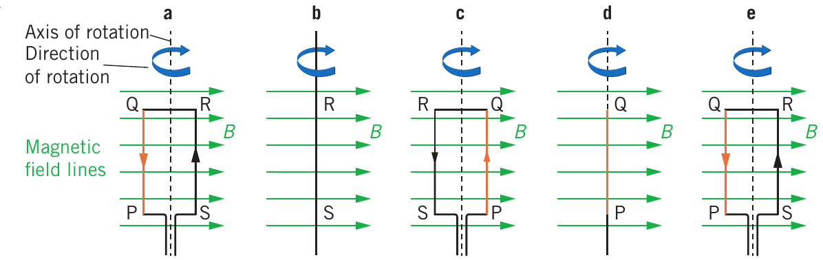
The diagram above shows five key positions (labelled a to e) of a rectangular coil rotating in a uniform magnetic field:
- Position a: Coil is parallel to field lines - minimum flux but maximum rate of change
- Position b: Coil at 45° - flux increasing
- Position c: Coil perpendicular to field - maximum flux but zero rate of change
- Position d: Coil at 135° - flux decreasing but still positive
- Position e: Coil returns to parallel - minimum flux, maximum rate of change again
Understanding magnetic flux and induced EMF
Magnetic flux variation
The magnetic flux through a coil depends on three factors: the magnetic field strength , the area of the coil , and the angle between the magnetic field and the normal (perpendicular) to the coil's surface.
For a rotating coil, the magnetic flux is given by:
where:
- is the magnetic flux measured in webers (Wb)
- is the area of the coil in square metres (m²)
- is the magnetic field strength in tesla (T)
- is the angle between the field and the normal to the coil area
As the coil rotates through one complete cycle, the magnetic flux varies sinusoidally, following a sine wave pattern.
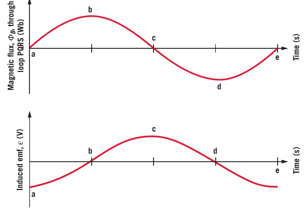
The top graph shows how magnetic flux varies with time as the coil completes one rotation. Notice:
- At position a and e: flux is zero (coil parallel to field)
- At position b: flux is maximum (coil perpendicular to field)
- At position d: flux is maximum but negative (coil perpendicular but opposite orientation)
- The variation follows the equation
Induced EMF and Faraday's law
According to Faraday's law of electromagnetic induction, the induced emf is proportional to the rate of change of magnetic flux:
This means the induced emf equals the negative gradient (slope) of the flux versus time graph.
The bottom graph in the figure above shows induced emf versus time. Key observations:
At position a: The flux is zero but changing most rapidly (maximum gradient). The magnetic field lines are switching from entering one side of the coil to entering the opposite side. Therefore, the magnitude of induced emf is maximum.
At position b: The flux is at its maximum value but momentarily constant (zero gradient). The coil is perpendicular to the field, so while flux is large, it's not changing at that instant. Therefore, the induced emf is zero.
At position c: The flux passes through zero again, with maximum negative gradient. The coil is momentarily parallel to the field. This produces maximum positive induced emf.
At position d: The flux reaches maximum negative value with zero gradient. The induced emf is zero again.
At position e: The flux is zero with maximum positive gradient. The induced emf is maximum and negative.
Phase Relationship Between Flux and EMF
The emf variation follows a cosine wave pattern, which is 90° out of phase with the flux sine wave. This phase shift is a direct consequence of the emf being proportional to the rate of change (gradient) of flux.
Remember: "Flux max, EMF relax" - maximum flux means zero emf (no change), while "Flux changing quick, EMF does the trick" - rapid flux change produces maximum emf.
Structure of a basic DC generator
A simple DC generator consists of several essential components working together to convert mechanical rotation into electrical energy.
Key components
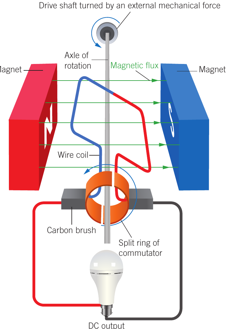
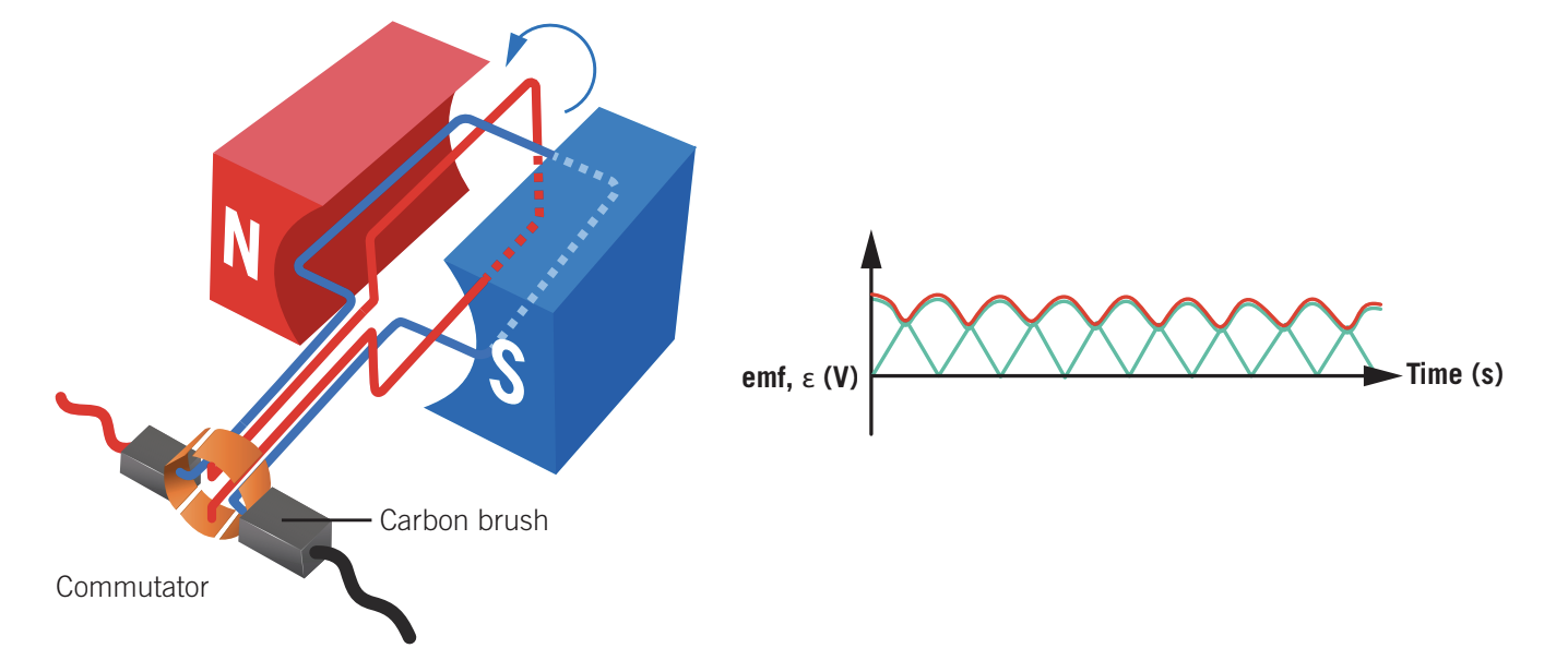
Field magnets: These create the uniform magnetic field in which the coil rotates. In the simple generator shown above, permanent magnets provide the magnetic field. The north pole (red) and south pole (blue) create horizontal field lines between them.
Armature (rotor winding): This is the coil of wire that rotates in the magnetic field. As it spins, the changing magnetic flux through the coil induces an emf. The coil is mounted on an axle that can be turned by an external mechanical force.
Split ring commutator: This is a crucial component that distinguishes a DC generator from an AC generator. The split ring is a cylindrical conductor divided into two halves (coloured orange in the diagram), with a small gap between them. Each end of the rotating coil connects to one half of the split ring.
Carbon brushes: These are spring-loaded contacts that touch the split ring as it rotates. They provide the electrical connection between the rotating coil and the external circuit. Carbon is used because it conducts electricity while also being soft enough to avoid excessive wear on the commutator.
External circuit: This is connected to the carbon brushes and receives the DC output. In the diagram, this is represented by a light bulb, demonstrating that the generator can supply power to a load.
Drive shaft: This provides the mechanical input energy. An external force (such as a person turning a handle, or in practical applications, a turbine or engine) rotates the shaft, which turns the armature.
The role of the split ring commutator
The split ring commutator is the key to producing DC rather than AC output. As the coil rotates, the emf induced in it alternates direction every half rotation - this is AC. However, the split ring commutator reverses the external connections every half cycle, ensuring that the current always flows in the same direction through the external circuit.
How the Split Ring Commutator Works
Here's the step-by-step process:
- During the first half rotation, one brush contacts one segment of the split ring
- During the second half rotation, when the emf in the coil reverses, the same brush now contacts the other segment
- This switching happens precisely when the coil passes through the vertical position
- The result is that although the emf in the coil alternates, the emf at the brushes maintains the same polarity
Think: "Split ring flips, DC it ships" - the commutator reverses connections to produce DC.
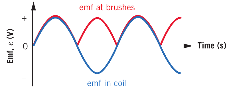
This graph clearly shows the difference between the emf generated in the coil (blue line showing AC) and the emf delivered to the external circuit via the brushes (red line showing rectified DC). The split ring commutator effectively "flips" the negative portions of the AC wave to become positive, producing pulsating DC.
Improving DC generator output
Single coil limitations
The output from a single coil DC generator, while being DC, is quite irregular - it pulses from zero to a maximum and back to zero twice per revolution. This pulsating output is not ideal for many applications.
Multiple coil generators
By using two or more coils positioned at angles to each other, the output can be made much smoother. When one coil is producing minimum emf, another coil can be at a position producing higher emf.
The diagram below shows a two-coil DC generator. The two coils are mounted at right angles (90°) to each other, and each has its own pair of split ring segments.
With two coils, the total output is much smoother than the individual coil outputs. The valleys in one coil's output are filled by the peaks from the other coil. Although some ripple remains, this configuration produces a more constant DC voltage.
For an even smoother output, practical DC generators use many coils (typically eight or more pairs) distributed evenly around the rotating armature. This produces an output that is very close to constant DC.
Practical DC generators
Real-world DC generators incorporate several improvements over the simple single-coil design to increase efficiency and output.
Multiple windings
Rather than a single loop of wire, practical generators use coils with many turns. A typical DC generator armature might have 60 to 1000 turns of wire wound around a soft iron core. The soft iron core serves two purposes:
- It provides mechanical support for the coil windings
- It concentrates the magnetic field, increasing the flux through the coils
Voltage Multiplication Effect
Multiple turns multiply the induced emf. If a single turn produces an emf of 0.1 V, then 100 turns will produce 10 V (assuming they're all wound in the same direction).
Electromagnets for field generation
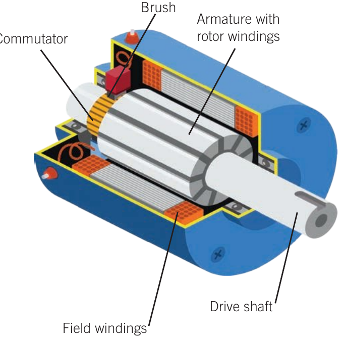
Most practical DC generators use electromagnets to create the magnetic field rather than permanent magnets. These are called field windings in the diagram below.
Advantages of Electromagnets
1. Stronger magnetic fields: Electromagnets can produce much stronger fields than permanent magnets, leading to greater induced emf and more electrical power output.
2. Self-excitation: Some of the current produced by the generator can be fed back to power the electromagnets. This is called self-excitation. Once the generator starts producing current (using residual magnetism in the iron cores), this current strengthens the magnetic field, which in turn increases the generated current. This positive feedback continues until the generator reaches its operating voltage.
3. Field control: The strength of the magnetic field can be adjusted by varying the current through the field windings, allowing control over the generator's output voltage.
Multiple commutator segments
Practical generators use commutators with many segments (not just two halves). In the cutaway diagram above, you can see the commutator has multiple copper segments separated by small gaps. With eight pairs of armature windings, there would be 16 commutator segments. This produces a much smoother DC output with minimal ripple.
Real applications
Before alternators became standard in vehicles, DC generators (often called dynamos) were used in cars to charge the battery and power electrical systems. Modern applications include:
- DC power supplies in industrial settings
- Battery charging systems
- Electric motor speed control systems
- Regenerative braking in trams and trains
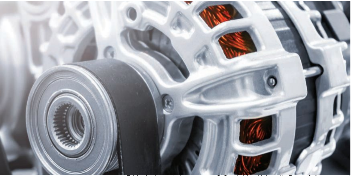
The image above shows a modern automotive alternator (which produces AC that is then rectified to DC electronically). The copper wire coils visible through the ventilation slots demonstrate the complexity of practical generator design.
Visualising coil rotation and flux changes
Understanding how magnetic flux changes as a coil rotates requires visualising the coil from different perspectives. This skill is essential for analysing generator operation.
Side view analysis
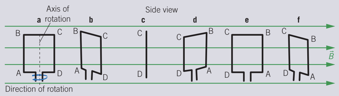
When viewing a rotating coil from the side (perpendicular to the axis of rotation), you see the coil profile change from a rectangle to a line and back. The six positions shown (labelled a to f) represent different orientations during one complete rotation.
However, from this viewpoint, it's difficult to clearly see how much of the coil's area is perpendicular to the magnetic field at each position.
Top view analysis
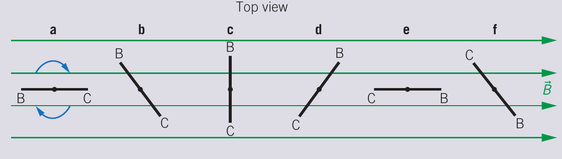
Viewing from the top (along the axis of rotation) makes the relationship much clearer. We can focus on just the edge of the coil closest to us (edge BC) to understand the flux changes:
- Position a: Edge BC is tilted, moving rapidly through field lines - flux is small but changing fast
- Position b: Edge BC perpendicular to field - flux increasing toward maximum
- Position c: Edge BC fully perpendicular - maximum flux, momentarily constant
- Position d: Edge BC perpendicular again - flux at maximum but from opposite side
- Position e: Edge BC tilted opposite direction - flux small but changing rapidly
- Position f: Cycle complete, returning to starting orientation
Corresponding graphs
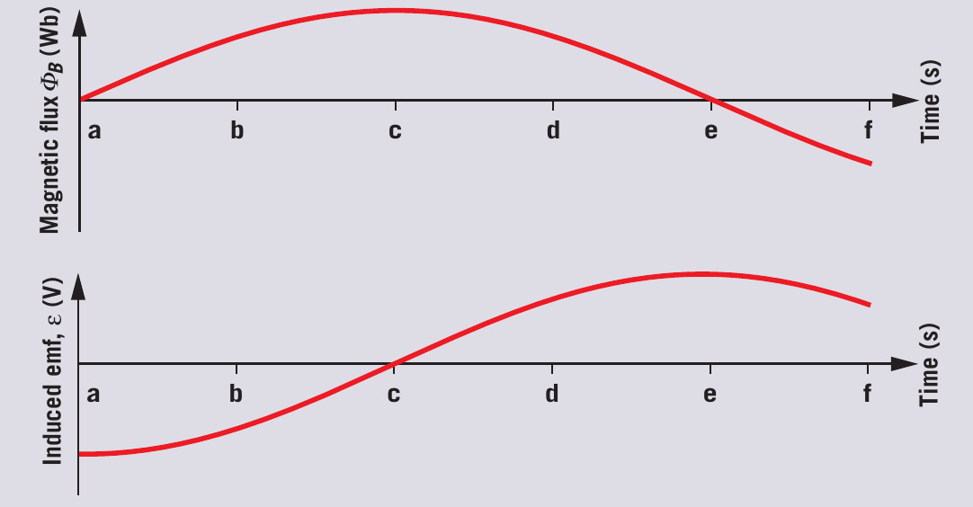
The top graph shows magnetic flux versus time. Notice:
- Flux follows a smooth curve (actually a sine wave)
- Maximum at positions near c and d
- Zero at positions a, e, and f
- Changes slowly near maximum values
- Changes rapidly when passing through zero
The bottom graph shows induced emf versus time. Notice:
- EMF follows a different curve (cosine wave)
- Maximum when flux is changing most rapidly (positions a, e, f)
- Zero when flux is momentarily constant (positions c and d)
- The relationship is a negative gradient:
Exam Strategy: Multiple Perspectives
When analysing generator problems, sketch both side and top views if possible. The top view makes it much easier to determine when flux is maximum/minimum and when it's changing most rapidly. This visualization technique is often the key to solving complex problems correctly.
Worked example: voltage output of a DC generator
Worked Example: Determining Generator Output Pattern
Question: A model motor is set up as a DC generator, with the output connected to a voltmeter and oscilloscope via a split ring commutator. The coil is rotated by hand.
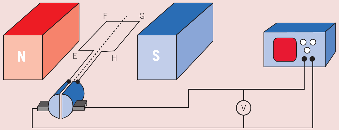
An oscilloscope (cathode ray oscilloscope or CRO) displays a graph of emf plotted against time. Which graph best shows the voltage output as the coil rotates steadily? At , the coil is horizontal as shown in the diagram.
Solution:
Step 1: Analyse initial conditions at
The coil is horizontal (parallel to the magnetic field). This means:
- The magnetic flux through the coil is zero (no field lines pass perpendicularly through it)
- The flux is changing most rapidly at this instant
- By Faraday's law, the emf will be maximum at
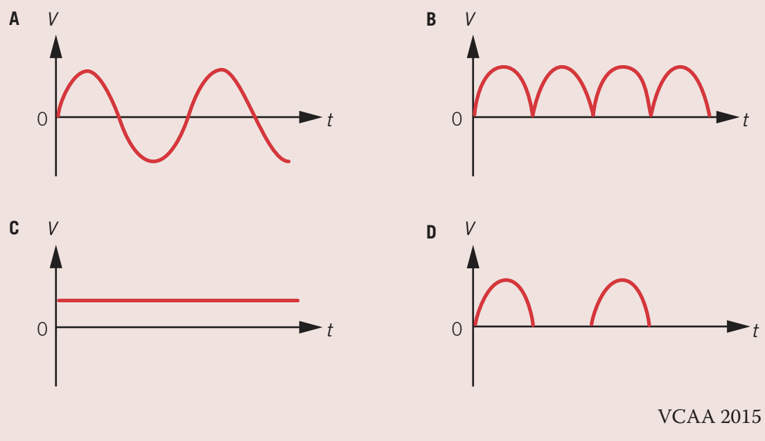
This immediately eliminates options C (which shows zero voltage at ) and D (which also starts at zero).
Step 2: Determine expected variation pattern
As the coil rotates steadily:
- The emf should vary sinusoidally (following a sine or cosine pattern)
- The emf reaches maximum when flux is zero and changing rapidly
- The emf falls to zero when flux is maximum and momentarily constant
Step 3: Consider the effect of the split ring commutator
- Without a commutator, the emf would alternate positive and negative (option A)
- The split ring commutator reverses the connections every half cycle
- This "flips" the negative portions to become positive
- The result is pulsating DC that never goes negative (option B)
Answer: B
Option B correctly shows:
- Maximum voltage at (when coil is horizontal)
- Sinusoidal variation in magnitude
- All values positive (rectified by commutator)
- Regular pulsing pattern characteristic of single-coil DC generator
Key takeaways
Essential Concepts to Remember
-
A DC generator converts mechanical energy into electrical energy using electromagnetic induction, producing direct current through the use of a split ring commutator.
-
The magnetic flux through a rotating coil varies sinusoidally according to . Maximum flux occurs when the coil is perpendicular to the field; minimum flux when parallel.
-
The induced emf is proportional to the rate of change of flux (Faraday's law). Maximum emf occurs when flux is changing most rapidly (coil parallel to field); zero emf when flux is momentarily constant (coil perpendicular to field). The emf and flux graphs are 90° out of phase.
-
The split ring commutator is essential for DC generation. It reverses the external connections every half rotation, converting the alternating emf in the coil into pulsating DC in the external circuit.
-
Practical improvements in real DC generators include: multiple coils positioned at different angles for smoother output, many turns of wire on soft iron cores for higher voltage, and electromagnets with self-excitation for stronger magnetic fields.