Generating EMF by Varying the Magnetic Flux (VCE SSCE Physics): Revision Notes
Generating EMF by Varying the Magnetic Flux
Introduction to electromagnetic induction
Electromagnetic induction is a fundamental principle underlying most modern electricity generation. This process allows us to convert mechanical energy into electrical energy, making it the basis for generators in wind farms, wave power stations, coal-fired power plants, nuclear facilities, and even geothermal energy systems.
The principle works through the interaction between magnetic fields and electrical conductors. When a conductor moves through a magnetic field, or when a magnetic field changes near a conductor, an electric current is produced. This discovery, made independently by Michael Faraday and Joseph Henry in 1831, revolutionised our ability to generate electricity on demand.
Real-World Application: Wave Energy
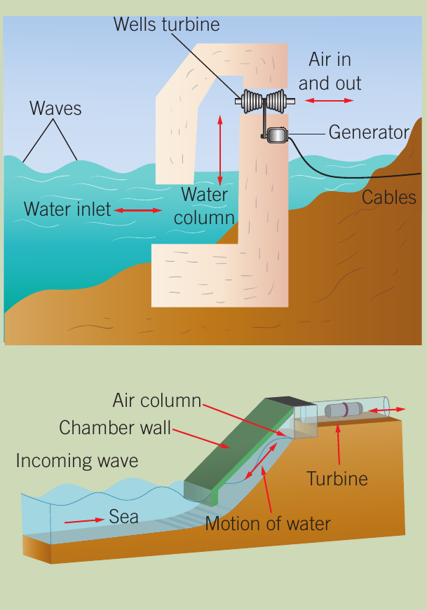
Wave energy converters demonstrate electromagnetic induction in action. These systems use the oscillating motion of ocean waves to drive turbines. As waves rise and fall, they force air through chambers containing turbines, which then rotate generators to produce electricity. This technology shows how changing magnetic flux can reliably generate electrical power from renewable sources.
Understanding electromagnetic induction
Electromagnetic induction occurs when a changing magnetic field near a conductor creates an electric current in that conductor. The key requirement is relative motion or change - either the magnetic field must change, or the conductor must move through the field.
The basic experiment
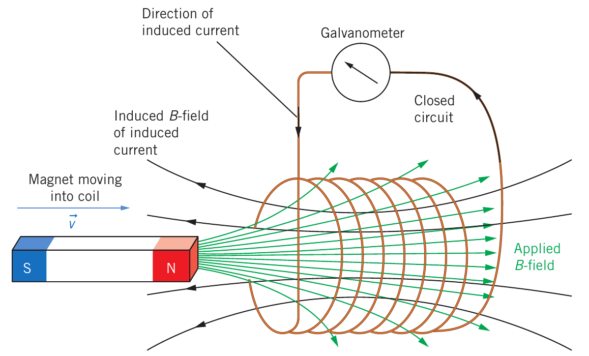
Consider a simple experiment with a bar magnet and a coil of wire connected to a galvanometer (a sensitive current-measuring device):
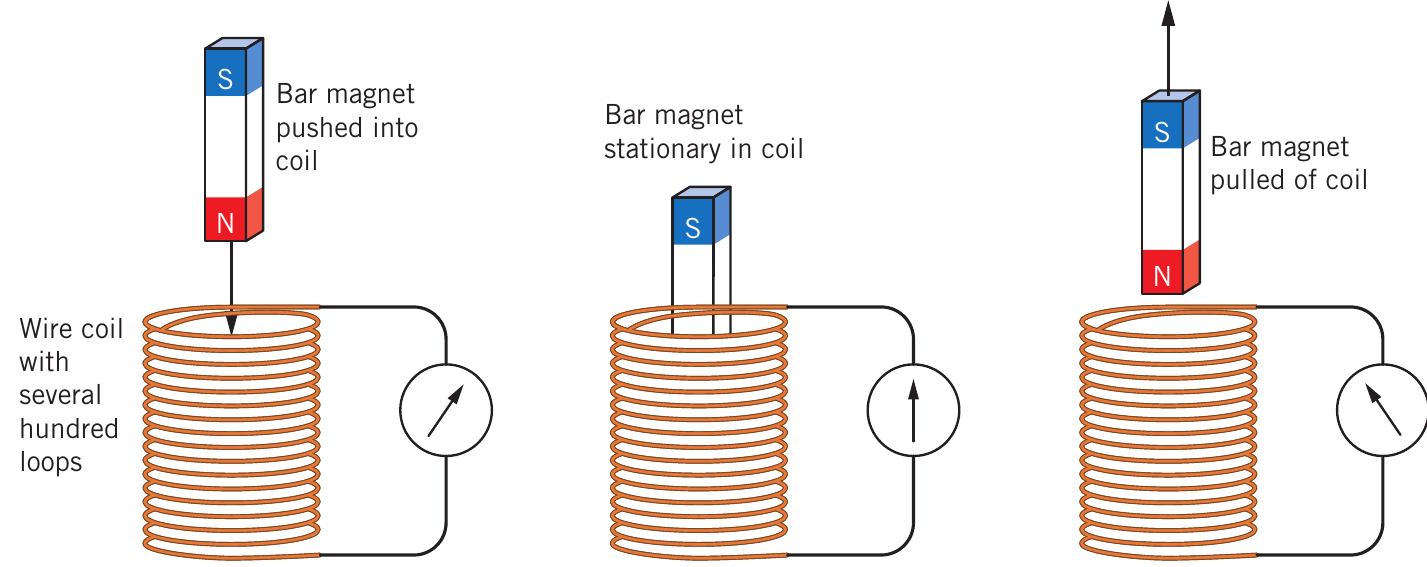
When the bar magnet is pushed into the coil, the galvanometer needle deflects, indicating current flow. When the magnet remains stationary inside the coil, no current flows. When the magnet is pulled out, current flows again but in the opposite direction.
Three Crucial Observations:
- Current is only generated when there is relative motion between the magnet and coil
- The faster the motion, the larger the current produced
- The direction of current depends on the direction of motion
These principles form the foundation for understanding all electromagnetic induction phenomena.
How charges respond to magnetic fields
To understand why current flows, we need to consider what happens to charged particles in a moving conductor. When a copper rod moves through a magnetic field, the charges within it experience a force given by , where is the charge, is the velocity, and is the magnetic field strength.
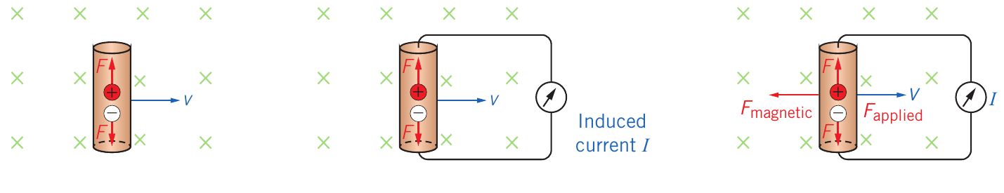
This force pushes positive charges in one direction and negative charges (electrons) in the opposite direction. Since electrons are free to move in metals while positive ions are fixed in the crystal lattice, electrons accumulate at one end of the rod. This separation of charge creates a potential difference - an induced electromotive force (emf).
When the rod is connected to a complete circuit with a galvanometer, this induced emf causes current to flow. However, maintaining this current requires continuous applied force because the flowing current itself creates a magnetic force that opposes the motion (as predicted by Lenz's law, which we'll explore later).
Magnetic flux
To properly understand electromagnetic induction, we need to introduce the concept of magnetic flux, symbolised as .
Definition and concept
Magnetic flux represents the total magnetic field passing through a given area. You can visualise this as counting the number of magnetic field lines that pass through a surface. The more field lines pass through, the greater the magnetic flux.
Visualising Magnetic Flux
Think of magnetic flux as counting field lines passing through a surface - like counting raindrops falling through a window. A larger window (area) catches more rain, and heavier rainfall (stronger field) means more drops pass through.
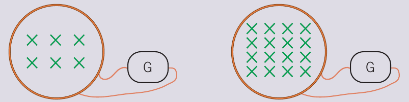
Magnetic flux depends on two key factors:
- The strength of the magnetic field (, perpendicular to the surface)
- The area () through which the field passes
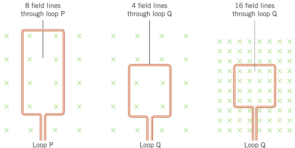
In the diagram above, loop P has twice the area of loop Q. When both loops are in the same magnetic field, loop P has twice the magnetic flux (8 field lines compared to 4). Similarly, if we place loop Q in a field four times stronger, the magnetic flux through it increases by a factor of four (from 4 to 16 field lines).
The magnetic flux formula
The relationship between magnetic flux, field strength, and area is expressed as:
Where:
- = magnetic flux (measured in tesla metre squared, T m², or weber, Wb)
- = magnetic field strength perpendicular to the surface (tesla, T)
- = area of the loop or surface (square metres, m²)
The unit weber (Wb) is defined as 1 Wb = 1 T m². This tells us that magnetic field strength can also be understood as magnetic flux density - the flux per square metre.
Why magnetic flux matters for induction
The Critical Insight
It's not the magnetic flux itself that generates current, but rather changes in magnetic flux. When the bar magnet approaches the coil in our earlier experiment, the magnetic field through the coil increases, meaning the magnetic flux increases. This change induces the current we observe.
When the magnet is stationary, there is no change in flux, and therefore no induced current. When we remove the magnet, the flux decreases, again producing current but in the opposite direction.
Induced EMF and Faraday's law
What is EMF?
The term electromotive force (abbreviated as emf, symbol ) is somewhat misleading because it's not actually a force. Rather, emf represents the potential difference between the terminals of an energy source when no current flows to an external circuit. It's measured in volts (V), just like potential difference.
Any device that converts one form of energy into electrical energy is a source of emf:
- Batteries convert chemical energy to electrical energy
- Solar cells convert light energy to electrical energy
- Generators convert mechanical energy to electrical energy
In electromagnetic induction, a changing magnetic flux through a conductor creates an induced emf, whether or not there's a complete circuit for current to flow.
Faraday's observations
Through careful experimentation, Michael Faraday discovered that the magnitude of induced emf depends on:
- How quickly the magnetic flux changes - faster changes produce larger emf
- How much the magnetic flux changes - greater changes produce larger emf
- The number of loops or turns in the coil - more loops multiply the effect
He quantified this as: the magnitude of induced emf is directly proportional to the rate of change of magnetic flux.
The rate of change of magnetic flux is calculated by dividing the change in flux by the time taken for that change:
Where is the change in magnetic flux and is the time interval over which it changes.
Mathematical expression
For a single loop of wire, Faraday's law states:
For a coil with loops, the induced emfs from each loop add together:
This means that:
- Using a stronger magnet (larger change in flux) increases the induced emf
- Moving the magnet faster (smaller time interval) increases the induced emf
- Using more loops in the coil multiplies the induced emf by
Lenz's law - determining the direction
While Faraday's law tells us the magnitude of induced emf, it doesn't tell us the direction of the induced current. This was determined by Heinrich Lenz in 1834.
The principle of opposition
Lenz's law states that: the magnetic flux of the induced current through a loop opposes the change in the applied magnetic flux that produced it.
Why Opposition is Essential: Energy Conservation
This might sound abstract, but it follows logically from energy conservation. If the induced flux helped rather than opposed the change causing it, we would get a runaway effect: more flux change → more current → even more flux change → even more current, creating unlimited energy from nothing. This violates conservation of energy, so the induced flux must oppose the change.
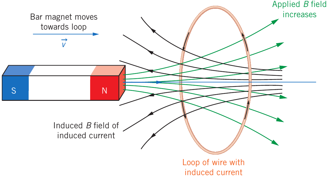
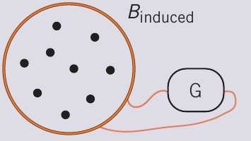
In the diagram above, as the north pole of a bar magnet approaches a wire loop:
- The applied magnetic field (green arrows) to the right increases
- This increasing flux induces a current in the loop
- The induced current creates its own magnetic field (black arrows) to the left
- This induced field opposes the increase in applied flux
Complete formula including direction
Lenz's law requires us to include a negative sign in Faraday's law to represent this opposition:
Where:
- = induced emf (volts, V)
- = number of turns or loops in the coil
- = change in magnetic flux (weber, Wb)
- = time taken for the change (seconds, s)
- The negative sign indicates that the induced emf produces a magnetic flux opposing the change
This complete statement combining both Faraday's law and Lenz's law is fundamental to understanding all forms of electromagnetic induction. The negative sign is not just mathematical notation - it represents the physical principle that induced effects always oppose their causes.
Determining current direction
To determine the direction of induced current in a circuit, follow this reasoning:
Step-by-Step Method for Finding Current Direction:
-
Identify the change: Is the applied magnetic flux through the loop increasing or decreasing?
-
Apply Lenz's law: The induced current will create a magnetic field that opposes this change
- If flux is increasing, induced field opposes the increase (points opposite direction)
- If flux is decreasing, induced field opposes the decrease (points same direction to maintain flux)
-
Use the right-hand grip rule: Once you know the direction of the induced magnetic field, curl your right hand's fingers in the direction of the field lines inside the coil. Your thumb points in the direction of current flow.
Memory aid for coil polarity
There's a useful visual pattern for remembering which end of a coil acts as a north or south pole:
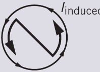
Visual Pattern for Coil Polarity
When viewing a coil end-on:
- Anticlockwise current → the letter N appears in the arrow pattern → north pole
- Clockwise current → the letter S appears in the arrow pattern → south pole
This pattern works because magnetic field lines point away from north poles and toward south poles, matching the direction implied by the current arrows.
Visualising changes from different perspectives
A critical skill for understanding electromagnetic induction is being able to visualise the same situation from multiple viewpoints. Different perspectives make different aspects of the problem clearer.
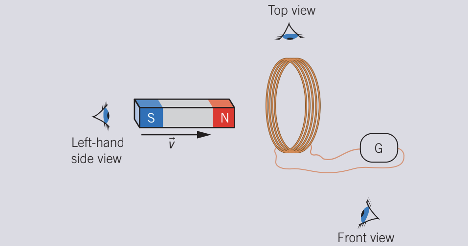
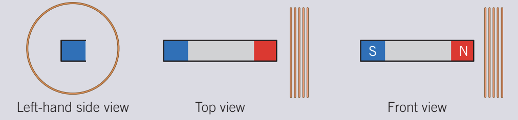
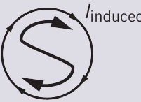
Consider a bar magnet approaching a coil connected to a galvanometer:
- Top view: Shows the circular coil and motion of the magnet toward it
- Left-hand side view: Best for seeing the change in flux through the coil - the number of field lines (×) through the coil increases as the magnet approaches
- Front view: Shows the magnet and coil from the side
Choosing the Best Perspective
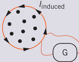
The left-hand side view is particularly useful because it clearly displays how the magnetic flux through the coil changes. We represent the applied magnetic field as × symbols (field into the page). As the north pole approaches, more × symbols appear in the coil area, representing increasing flux.
Using Lenz's law, if the applied flux (into the page) is increasing, the induced current must create flux out of the page (● symbols) to oppose this change. Applying the right-hand grip rule to this induced field direction tells us the current flows anticlockwise when viewed from the left.
Worked example: Calculating flux and induced EMF
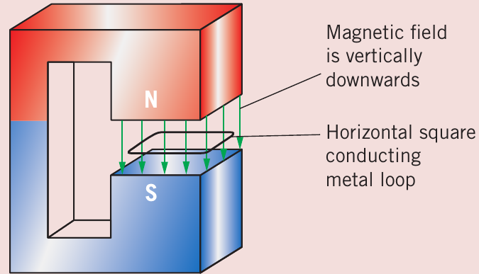
Worked Example: Square Loop in Magnetic Field
A square conducting metal loop with area 0.4 m² is positioned completely within a uniform magnetic field of strength 1.0 T pointing vertically downward.
Part a): Calculate the magnetic flux through the loop.
Using the magnetic flux formula:
The magnetic flux through the loop is 0.4 Wb.
Part b): The loop is pulled steadily to the right, completely leaving the magnetic field region in 5 seconds. Calculate the induced emf.
Initially the flux is 0.4 Wb. Finally, when the loop is completely outside the field region, the flux is 0 Wb. Therefore:
Using Faraday's law (for a single loop, ):
The induced emf is 0.08 V or 80 mV.
Part c): Describe the direction of induced current.
The negative sign in Faraday's law tells us that the induced emf opposes the change. Here, the downward magnetic flux through the loop is decreasing (from 0.4 Wb to zero).
By Lenz's law, the induced current must create a downward magnetic field to oppose this decrease. Using the right-hand grip rule, if we want a downward magnetic field inside the loop, the current must flow clockwise when viewed from above.
Key applications in generators
The principles we've studied form the basis of all electromagnetic generators:
Alternators (AC generators) use rotating coils in magnetic fields or rotating magnets near stationary coils. As the coil rotates, the magnetic flux through it continuously changes, inducing an alternating emf that produces AC current.
Dynamos (DC generators) use similar principles but include a commutator to convert the alternating current to direct current.
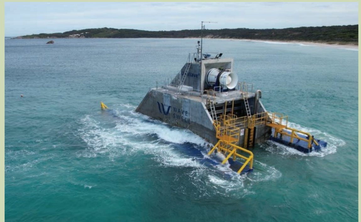
Wave generators like the UniWave system use the oscillating motion of waves to repeatedly change magnetic flux through coils, generating AC electricity efficiently.
Common Design Principles
All electromagnetic generator systems rely on:
- Maximising the rate of change of flux (faster rotation or movement)
- Using multiple loops to multiply the induced emf
- Minimising resistance to allow larger currents
Understanding these principles helps explain why generators are designed with specific features like high-speed rotation and many-turn coils.
Exam tips
Key Strategies for Electromagnetic Induction Problems:
-
Always identify what's changing: Is it the magnetic field strength, the area in the field, or the angle between them?
-
Calculate flux before and after: Find explicitly rather than trying to use Faraday's law directly
-
Check your units: Magnetic flux is in Wb (or T m²), time in seconds, emf in volts
-
For direction questions: Start with "what flux change is occurring?" then ask "what must the induced field do to oppose this?"
-
Draw diagrams from useful viewpoints: Sometimes a top view is best, sometimes a side view shows the flux change more clearly
-
Remember the minus sign means opposition: The induced effect always works against the change causing it
Remember!
Essential Concepts to Master:
-
Electromagnetic induction occurs when a changing magnetic flux induces an emf in a conductor - either the field changes, or the conductor moves through the field
-
Magnetic flux () represents the total magnetic field through an area, measured in weber (Wb)
-
Faraday's law states that induced emf is proportional to the rate of change of magnetic flux:
-
Lenz's law (the minus sign) means the induced current creates a magnetic field that opposes the change causing it - this follows from energy conservation
-
The direction of induced current can be found by determining what magnetic field would oppose the flux change, then applying the right-hand grip rule
-
All electromagnetic generators work by varying magnetic flux through coils to continuously induce emf