Generators With Slip Rings Produce Sinusoidal AC (VCE SSCE Physics): Revision Notes
Generators With Slip Rings Produce Sinusoidal AC
Introduction to AC power generation
Wind energy is one of the most cost-effective renewable energy sources available for large-scale electricity generation. Wind has kinetic energy that can be converted into electrical energy through the use of wind turbines. These turbines have been used for centuries—originally for mechanical tasks like pumping water or grinding grain.
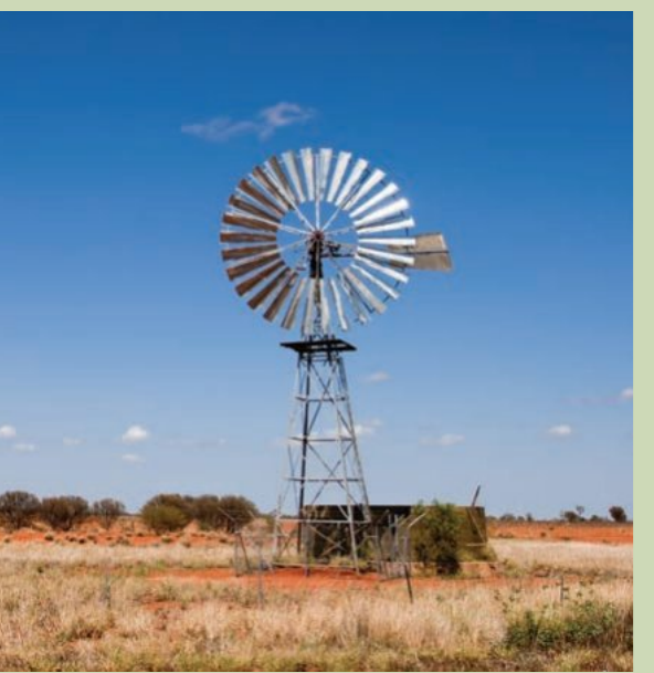
Modern wind turbines convert the kinetic energy of wind into electrical energy through an alternator (AC generator). While the theoretical maximum efficiency for extracting energy from wind is 59%, practical wind turbines typically achieve efficiencies between 40-50%.
This efficiency limitation exists because if the turbine extracted all the kinetic energy from the wind, the air would stop moving after passing through the blades, which is physically impossible. This theoretical maximum is known as the Betz limit.
A typical wind turbine consists of four main components:
- Blades: Longer blades can harvest more kinetic energy, even from gentle breezes
- Tower: Equipped with a yaw motor and sensors to orient the turbine into the wind
- Generator: Contains a gearing system that allows blades to rotate slowly while the alternator rotor spins rapidly
- Base: Provides structural support and houses control systems
The electrical output from wind turbines requires inverters and transformers to convert the power to high voltage suitable for transmission through the electrical grid.
How alternators work
An alternator is a device that generates alternating current (AC) by rotating a coil of wire within a magnetic field. While it operates on the same fundamental principle as a DC generator (electromagnetic induction), its commutator design is crucially different.
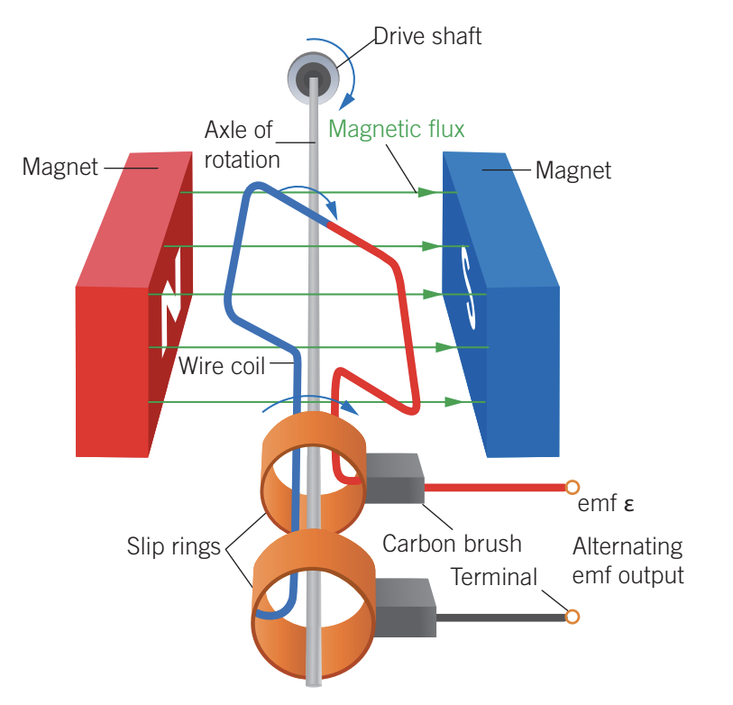
Structure and key components
A simple alternator consists of:
- A wire coil that rotates on an axle between two magnets
- Slip rings: Two copper rings that rotate with the axle, each connected to one end of the coil
- Carbon brushes: Spring-loaded contacts that press against the slip rings
- Terminals: External connection points for the alternating current output
The slip rings are electrically insulated from each other and rotate continuously with the coil. This is the key difference from DC generators, which use a split ring commutator.
Slip ring: A form of commutator used in alternators to connect the rotating coil to the non-rotating terminals, allowing the transfer of alternating current (AC) produced in the coil to the external circuit.
The difference between slip rings and split ring commutators
In a DC generator, the split ring commutator reverses the connections every half rotation, ensuring current always flows in the same direction in the external circuit. In an alternator, the slip rings maintain continuous connection to the same ends of the coil throughout rotation, allowing the natural alternation of current direction to be transmitted to the output.
This fundamental difference is what determines whether the generator produces DC or AC output.
Understanding the sinusoidal output
As the coil rotates in the magnetic field, both the magnetic flux through the coil and the induced electromotive force (EMF) vary in a characteristic pattern over time.
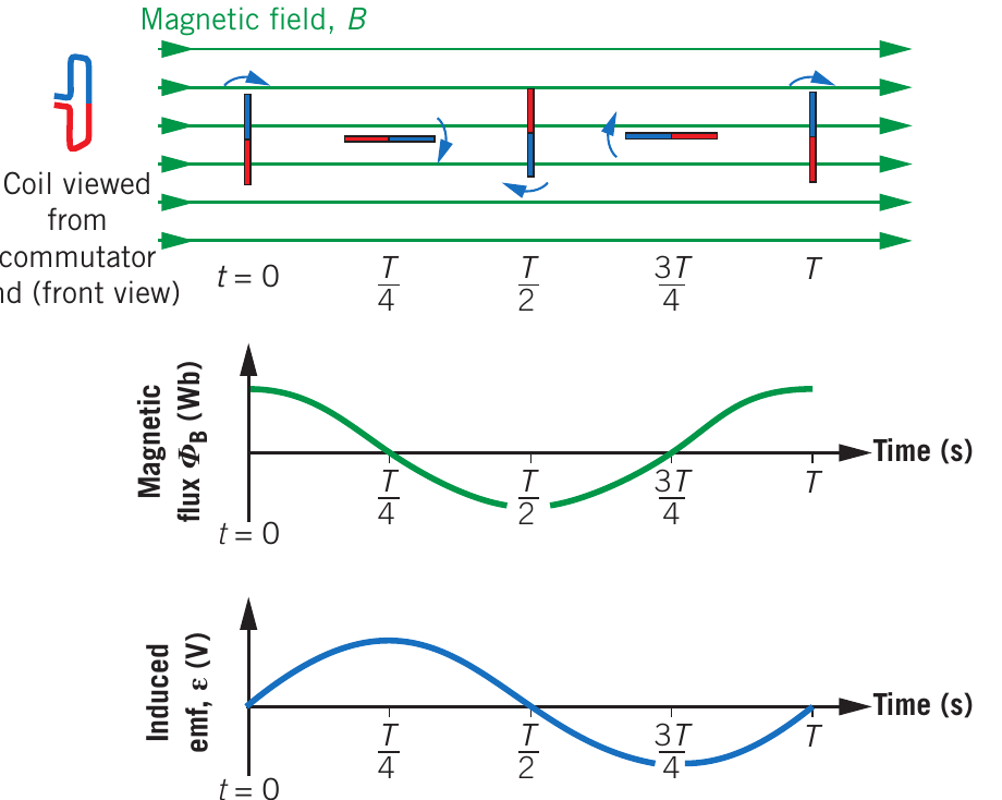
Magnetic flux variation
When the coil plane is perpendicular to the magnetic field lines (at and ), the magnetic flux through the coil reaches its maximum or minimum value. When the coil plane is parallel to the field lines (at and ), the flux through the coil is zero.
The magnetic flux varies sinusoidally with time, following the pattern:
where is the area of the coil, is the magnetic field strength, and is the angular velocity of rotation.
Induced EMF and its relationship to flux
According to Faraday's law, the induced EMF is proportional to the rate of change of magnetic flux:
where is the number of turns in the coil.
Key insight: The induced EMF is given by the negative gradient (slope) of the magnetic flux versus time graph. This means:
- Maximum EMF occurs when magnetic flux is zero ( and ), because this is when the flux is changing most rapidly
- Zero EMF occurs when magnetic flux is at its maximum or minimum (, , ), because at these points the flux is momentarily not changing
This relationship produces the characteristic sinusoidal (smooth wave-like) shape of AC voltage.
Factors affecting AC generator output
The output EMF from an alternator depends on several variables. Understanding these relationships helps predict how changes to the generator will affect its performance.
Proportional relationships
The induced EMF is directly proportional to:
1. Magnetic field strength ()
Doubling the field strength doubles the output EMF. A stronger magnetic field creates a greater rate of change of flux through the rotating coil.
2. Coil area ()
A coil with twice the area produces twice the EMF. Larger coils intercept more magnetic field lines, resulting in greater flux changes.
3. Number of turns ()
More loops in the coil directly increase the output voltage. Each additional turn contributes its own induced EMF, and these voltages add together in series.
These relationships can be understood intuitively—a stronger field, larger area, or more turns all increase the rate at which magnetic flux changes through the conductor.
Effect of rotation speed
Increasing the rotation speed has two effects:
- Doubles the amplitude (maximum voltage) of the output
- Halves the period (increases the frequency) of the oscillation
This occurs because faster rotation causes both a greater rate of change of flux and more frequent reversals in flux direction. If you double the rotation speed, you double the angular velocity , which doubles both the frequency and the maximum voltage output.
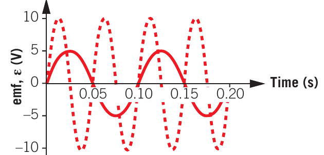
The graph above shows two EMF waveforms with the same frequency but different amplitudes, illustrating how one parameter can change while others remain constant.
Worked example: magnetic flux and voltage calculations
Worked Example: Calculating Flux and Voltage in a Rotating Coil
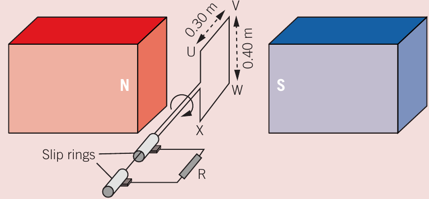
Problem setup: A rectangular coil (UVWX) measuring 0.30 m by 0.40 m consists of 20 turns of wire. It rotates in a uniform magnetic field of strength 1.5 T at 50 revolutions per second.
Part A: Calculating magnetic flux
To find the magnetic flux through each turn when the coil is perpendicular to the field:
Part B: Average voltage during quarter rotation
First, determine the time for 90° rotation:
- Complete revolution takes s
- Quarter revolution takes s = 0.005 s
Then apply Faraday's law:
Part C: Identifying flux variation
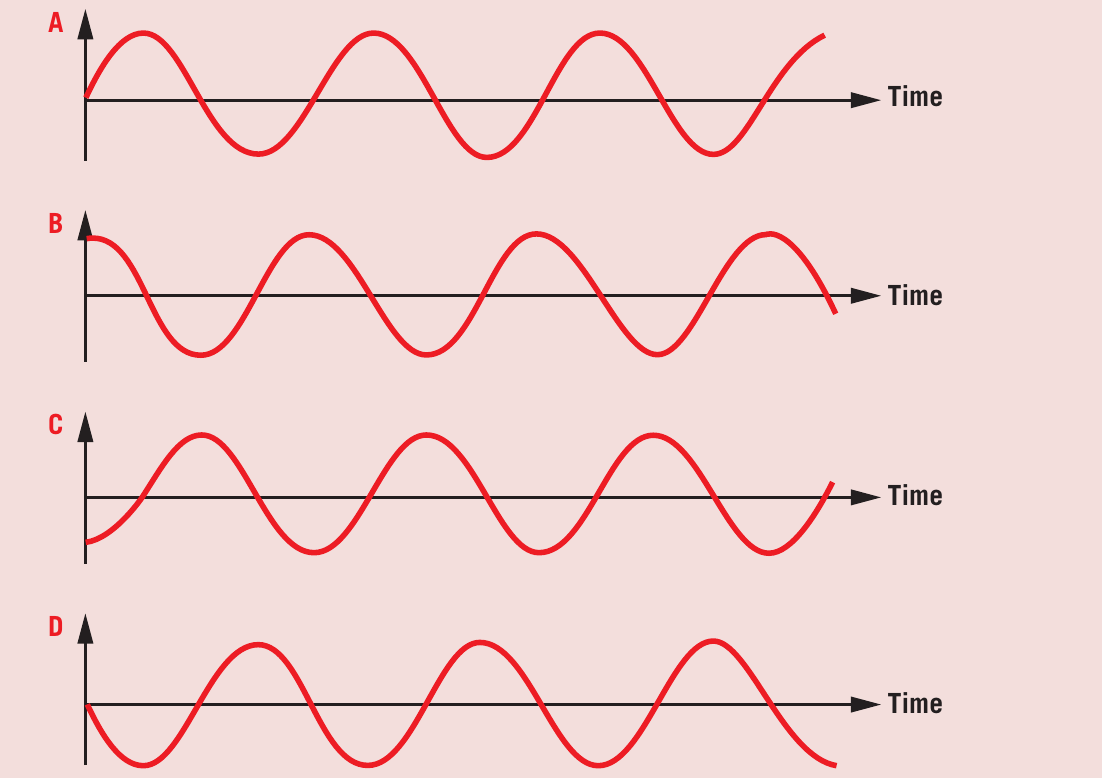
When the coil starts perpendicular to the field with flux in the positive direction (north to south), the flux begins at maximum positive value and decreases as the coil rotates. This corresponds to graph B, which shows a cosine wave starting at maximum.
Part D: Current direction analysis
At , the magnetic flux is at maximum but the rate of change is zero (the gradient of the flux-time graph is zero). Therefore, the induced EMF and current must be zero at this instant.
As the coil begins to rotate, flux decreases. By Lenz's law, the induced current opposes this change by creating additional flux in the same direction. Using the right-hand grip rule, this requires current to flow from V to U (the negative direction in the problem's convention).
The current must therefore start at zero and become negative, matching graph D.
Real-world alternators
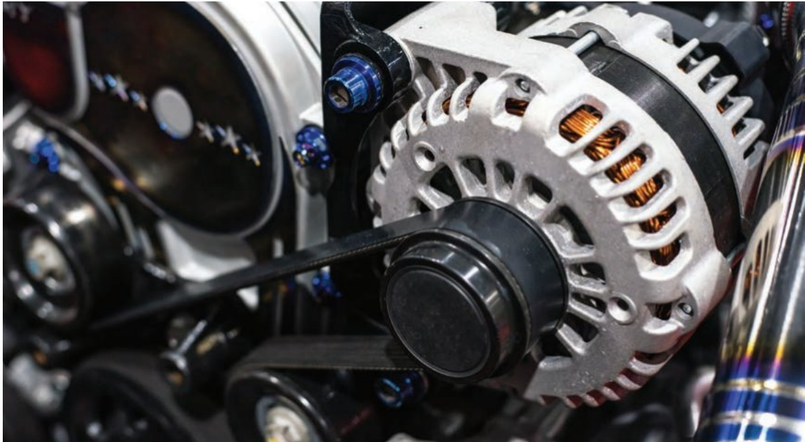
Practical alternators, such as those in vehicles or power stations, are more complex than the simple single-coil design described above. They contain:
- Multiple coils arranged around the rotating armature
- Many turns of wire in each coil to increase output voltage
- Sophisticated slip ring assemblies to handle higher currents
- Cooling systems to dissipate heat from electrical resistance
Despite these complications, the fundamental principle remains the same: rotating a coil in a magnetic field to produce sinusoidally varying AC voltage. The complexity serves to increase efficiency, power output, and reliability rather than changing the underlying physics.
Remember!
Key Points to Remember:
-
Slip rings are used in alternators to allow continuous electrical connection to a rotating coil, producing alternating current (AC) output. This differs from split ring commutators used in DC generators.
-
The induced EMF is proportional to the rate of change of magnetic flux. Maximum EMF occurs when flux is zero (changing most rapidly), and zero EMF occurs when flux is at maximum or minimum (momentarily not changing).
-
The EMF output follows a sinusoidal pattern described by , where the EMF equals the negative gradient of the flux-time graph.
-
Output voltage is directly proportional to magnetic field strength (), coil area (), and number of turns (). Doubling any of these parameters doubles the output.
-
Increasing rotation speed both doubles the amplitude and halves the period (doubles the frequency) of the AC output, because it increases both the rate of flux change and the frequency of flux reversals.