Useful Electronic Components (VCE SSCE Physics): Revision Notes
Useful Electronic Components
Introduction to semiconductor devices
The twentieth century saw an electrical revolution where semiconductor devices replaced older valve technology. Valves were large glass tubes filled with vacuum and metal components. They were expensive, fragile, and consumed significant power. From the 1960s onwards, semiconductors offered a better alternative - they are smaller, cheaper, more robust, and more efficient.

The transistor became one of the first mass-produced semiconductor devices. Portable battery-powered radios, commonly called "transistor radios", emerged in 1954. Before this, radios were large pieces of furniture that required mains power.
Modern semiconductor devices can detect changes in light levels, temperature, pressure, and other environmental factors. They draw minimal current and operate at low voltages, making them ideal for controlling electronic switches in circuits. These switches can then control external circuits with higher current and voltage requirements.
Today's technology - from mobile phones to satellites to medical nanobots - relies on integrated circuits (chips) built from semiconductor materials. Next time you notice streetlights turning on at dusk, think about how light sensors control these electrical circuits. When you open your fridge, remember the electrical systems that maintain the cool temperature all day.
Diodes
A diode is a semiconductor component made mainly from silicon, germanium or selenium, doped with impurities like phosphorus and aluminium. While the detailed physics of semiconductors is beyond this course, the key point is that semiconductors conduct electricity less well than metals, and their resistance depends on impurity distribution and temperature.
How diodes work
A diode has very different resistance depending on the direction of current flow:
- Forward-biased: When connected with positive terminal to one end and negative to the other, the diode has very low resistance and allows current to flow
- Reverse-biased: When the connections are reversed, the diode has very high resistance and blocks current flow
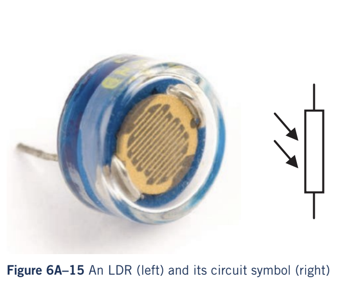
The circuit symbol reflects this function. The triangle acts like an arrow showing the direction current can flow, while the line across its end acts like a wall blocking current from the opposite direction.
Current-voltage (I-V) characteristics
Unlike ohmic resistors, diodes are non-ohmic and their I-V characteristic is asymmetric. The size and direction of current depends on which way the voltage is connected (the polarity).
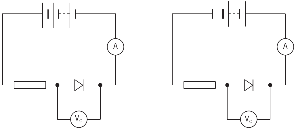
To measure the I-V characteristic, you need to:
- Set up a circuit with the diode, ammeter, and voltmeter
- Take readings with the diode forward-biased
- Reverse the power supply connections
- Take readings with the diode reverse-biased
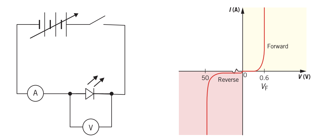
Key features of the diode I-V graph:
- Forward voltage (): Approximately 0.6-1.0 V for silicon diodes - this is the threshold voltage before significant current flows
- Reverse breakdown voltage (): Around 50 V or more - if this voltage is exceeded in reverse, the diode breaks down and conducts
Applications
Diodes have several practical uses:
- Protection: Preventing damage to components that cannot handle reverse current
- Rectification: Converting alternating current (AC) to direct current (DC), such as in laptop chargers
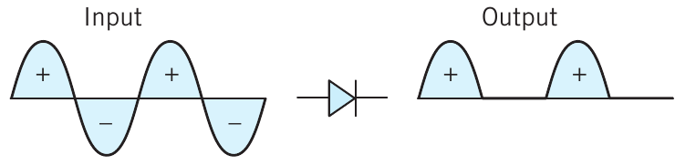
When AC voltage is supplied to a diode, only the forward-biased portions pass through. This is called half-wave rectification. However, this process only converts 50% of the electrical energy, as energy in the blocked half-cycles is wasted.
Safety note
Like all components, diodes have maximum current and voltage ratings. Exceeding these limits causes the diode to overheat, potentially melting or producing smoke. A small protective resistor is often placed in series with the diode to limit current and share some of the voltage drop.
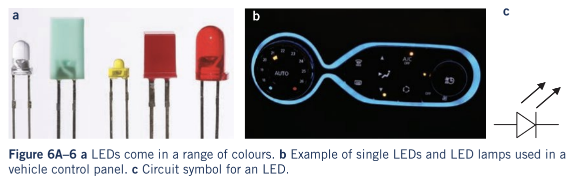
Light-emitting diodes (LEDs)
A light-emitting diode (LED) is a special type of diode that emits light when current flows through it in the forward direction. LEDs appear as indicator lights on electrical appliances and are increasingly used as efficient replacements for filament and fluorescent lighting.
Like standard diodes, LEDs:
- Have very low resistance when forward-biased (allowing current and producing light)
- Have very high resistance when reverse-biased (blocking current and producing no light)
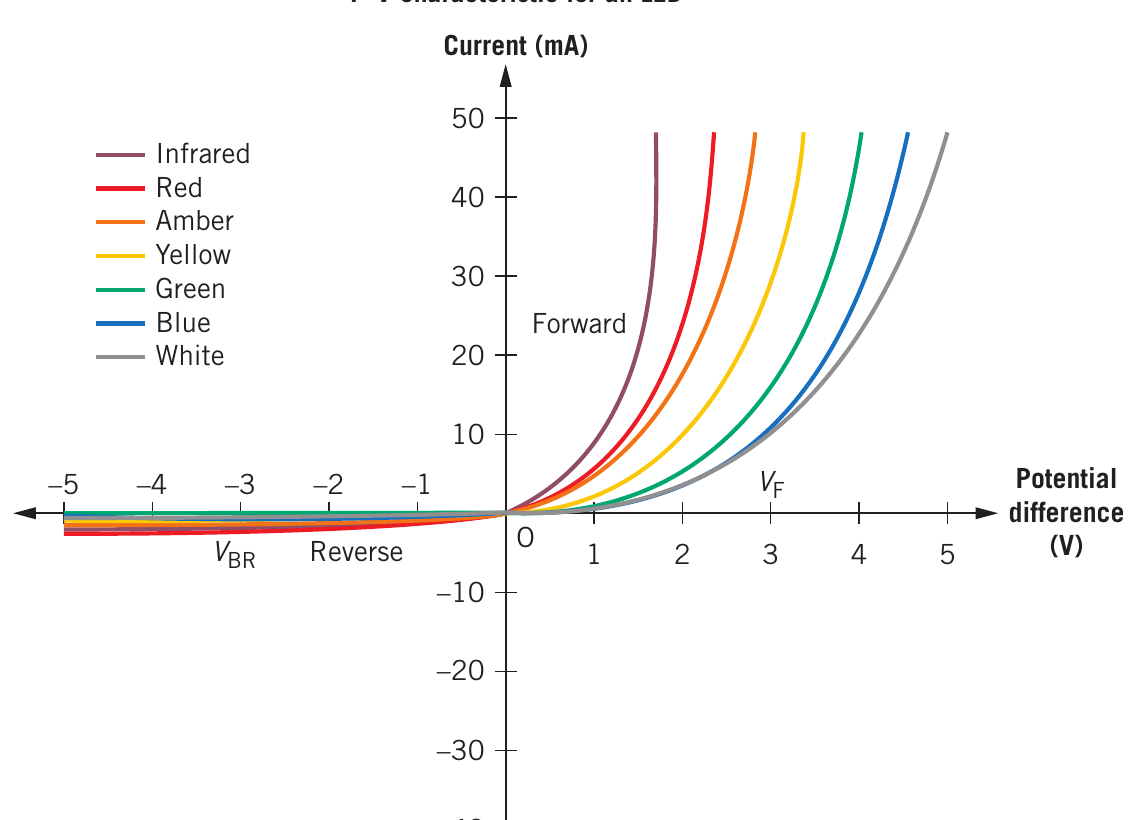
The I-V characteristics of LEDs are similar to standard diodes, but different colours have different forward voltage thresholds. This is because different semiconductor materials and doping produce different wavelengths of light.
Energy efficiency
LED lamps use significantly less energy than filament bulbs or fluorescents to produce the same amount of light. They are more efficient and have become cheaper to manufacture, making them central to the twenty-first century electrical revolution.
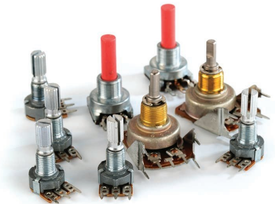
Potentiometers (variable resistors)
A potentiometer (often called a "pot") is a device with variable resistance. It consists of a long wire with high resistance, often coiled for convenience, with three terminals:
- Two fixed terminals at each end (A and C)
- One sliding contact (wiper) that can move along the wire (B)
The potentiometer can be used in different ways depending on which terminals are connected:
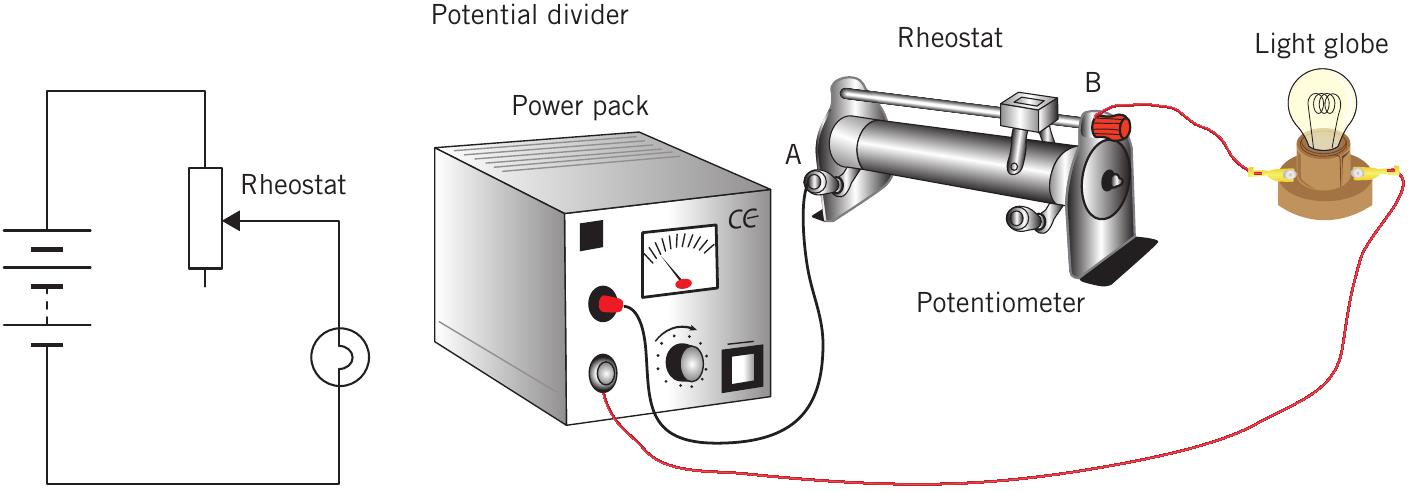
- Potential divider: Uses all three terminals to provide variable voltage
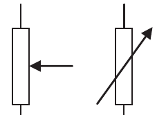
- Variable resistor (rheostat): Uses only two terminals to provide variable resistance
Potentiometer as potential divider
When all three terminals are connected, the potentiometer acts as a potential divider. The voltage at the wiper position depends on where it sits along the resistance wire.
Since the resistance wire obeys Ohm's law, the proportion of voltage is directly related to the proportion of length:
- Slider halfway:
- Slider three-quarters along:
- Slider one-quarter along:
Current flows through the entire length of the potentiometer in this configuration. When a load is connected to , it is effectively in parallel with the lower section of the potentiometer, drawing additional current from the power supply.
Applications: Volume controls, light dimmers
Potentiometer as variable resistor (rheostat)
When only two terminals are connected (one end and the slider), the potentiometer acts as a variable resistor. Only the selected portion of wire (A to B) is included in the circuit.
Moving the sliding contact changes the resistance in the circuit:
- Longer wire length = greater resistance = lower current
- Shorter wire length = lower resistance = greater current
The variable resistor is in series with the rest of the circuit, so moving the slider affects both current and voltage across components.
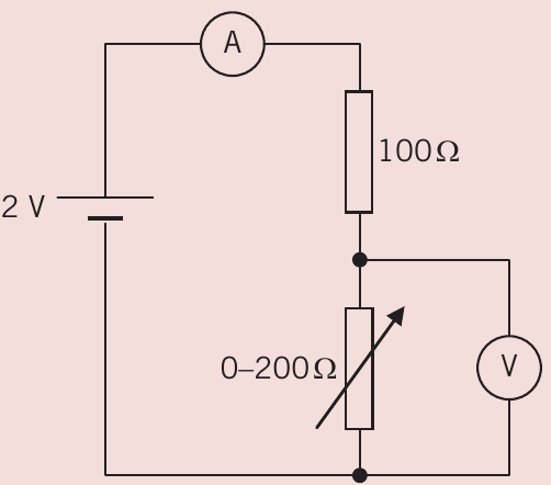
Worked example: Variable resistor
Worked Example: Variable Resistor Circuit Analysis
A circuit has a fixed 100 Ω resistor and a variable resistor adjustable between 0 and 200 Ω, connected to a 12 V supply.
Step 1: Maximum current (when variable resistor = 0 Ω):
In this case, V (no voltage drop across zero resistance)
Step 2: Minimum current (when variable resistor = 200 Ω):
Total resistance: Ω
Voltage across potentiometer: V
Light dependent resistors (LDRs)
A light dependent resistor (LDR) is a semiconductor device whose resistance changes with light intensity. The incident light might vary with:
- Distance from a light source
- Time of day (day to night)
- Opening or closing of doors or cupboards
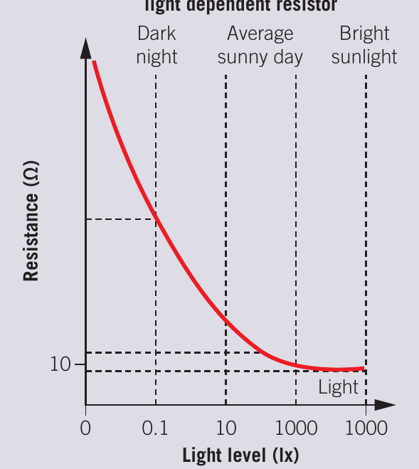
Resistance-light relationship
As light intensity increases, the resistance of an LDR decreases exponentially. This relationship is measured in units of lux (lx):
- Darkness (0.1 lx): Resistance approximately 10 MΩ (10,000,000 Ω)
- Average sunny day (100 lx): Resistance approximately 1 kΩ (1,000 Ω)
- Bright sunlight (1000 lx): Resistance approximately 10 Ω
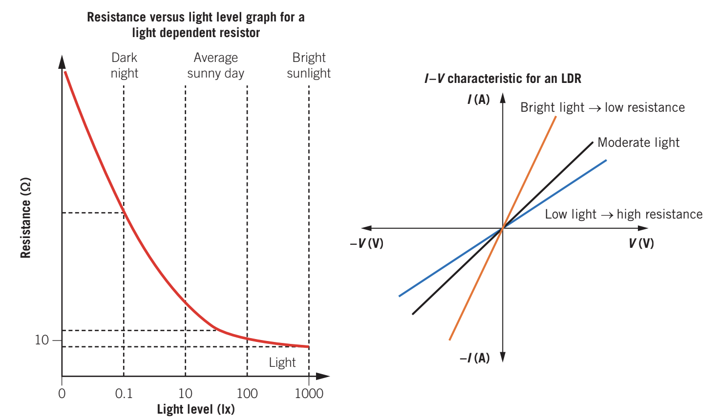
I-V characteristics
For a particular light intensity, an LDR behaves as an ohmic resistor over a small voltage range. The I-V characteristic shows:
- Bright light: Low resistance, steep slope through origin
- Moderate light: Medium resistance, medium slope
- Low light: High resistance, shallow slope
Applications
LDRs are used in many practical applications:
- Light meters: Measuring light intensity
- Automatic flash: Triggering camera flash in low light
- Streetlights: Turning on as it gets dark
- Night lights: Activating in darkness
- Burglar alarms: Detecting when a light beam is broken
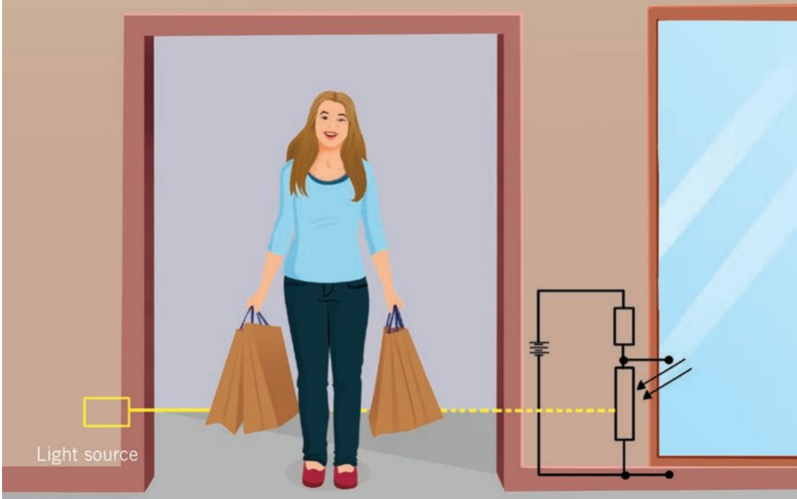
LDR in potential divider circuits
When an LDR is part of a potential divider circuit with a variable resistor, the switching light level can be adjusted. As the LDR resistance increases in darkness, a greater proportion of the supply voltage appears across it, which can trigger an electronic switch.
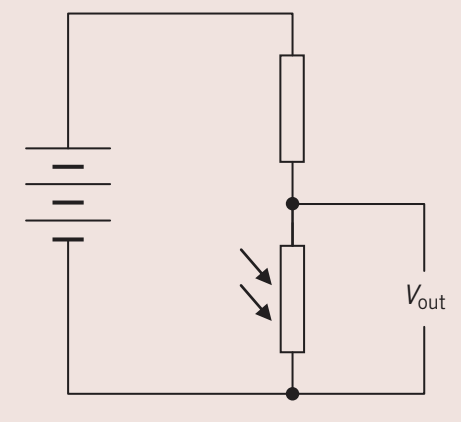
Worked Example: Nightlight Circuit
A nightlight circuit where increasing LDR resistance at dusk causes to rise and trigger a switch that turns on a light globe in an external circuit.
As darkness falls → LDR resistance increases → Greater voltage across LDR → rises → Switch triggers → Light turns on
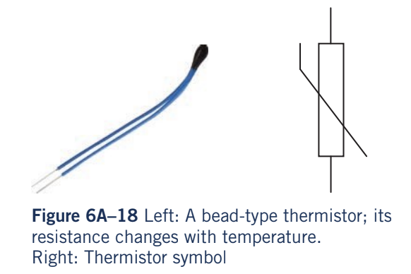
Thermistors
A thermistor (short for "thermal resistor") is a semiconductor device whose resistance changes with temperature. There are two main types:
Negative thermal coefficient (NTC) thermistor
This is the most common type. As temperature increases, resistance decreases exponentially. For example:
- At -25°C: Resistance approximately 100,000 Ω
- At 25°C: Resistance approximately 1,000 Ω
- At 125°C: Resistance approximately 1 Ω
Unless stated otherwise, assume a thermistor is NTC type.
Positive thermal coefficient (PTC) thermistor
As temperature increases, resistance suddenly increases steeply above a certain temperature (typically around 100°C). These are custom-designed for specific applications.
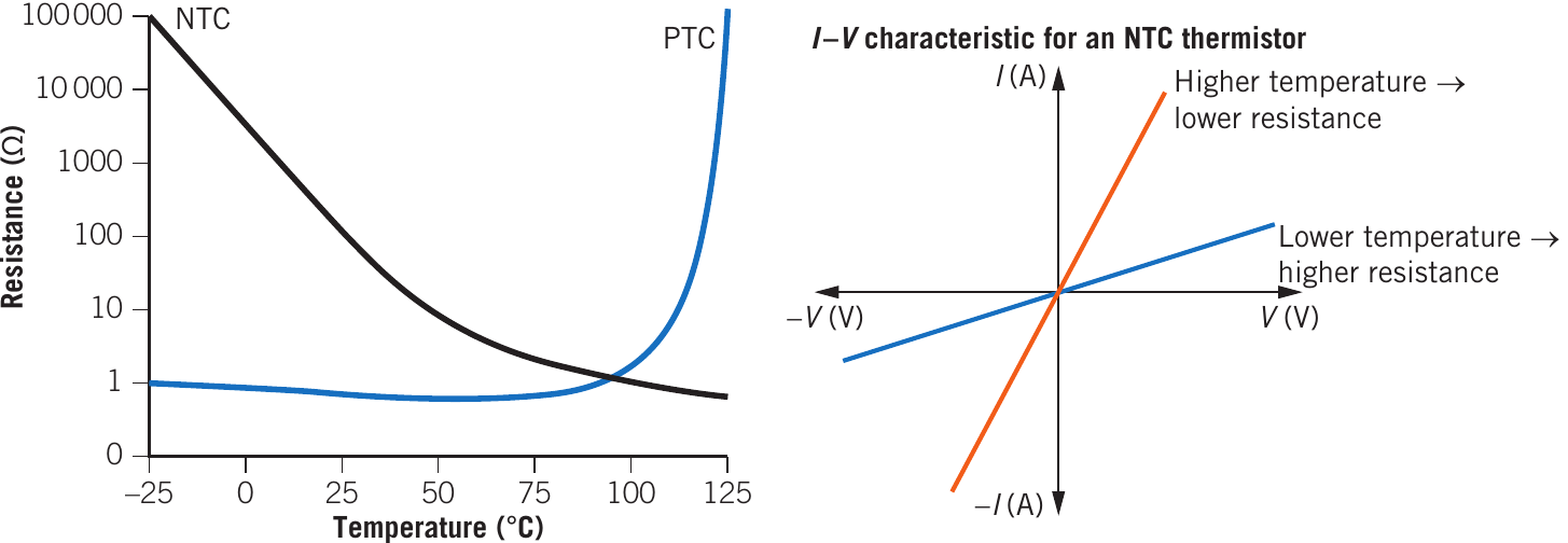
I-V characteristics
For a given temperature, most thermistors obey Ohm's law over a small voltage range. The I-V characteristic shows:
- Higher temperature: Lower resistance (for NTC), steeper slope
- Lower temperature: Higher resistance (for NTC), shallower slope
When measuring I-V characteristics, you must state the temperature at which measurements were taken.
Applications
Thermistors are used in temperature control and measurement:
- Heaters and air conditioners: Temperature regulation
- Refrigerators and ovens: Maintaining set temperatures
- Digital thermometers: Temperature measurement
- Engine temperature sensors: Monitoring vehicle temperatures
Thermistor in potential divider circuits
A thermistor in a potential divider can control circuits based on temperature. A variable resistor allows adjustment of the switching temperature.
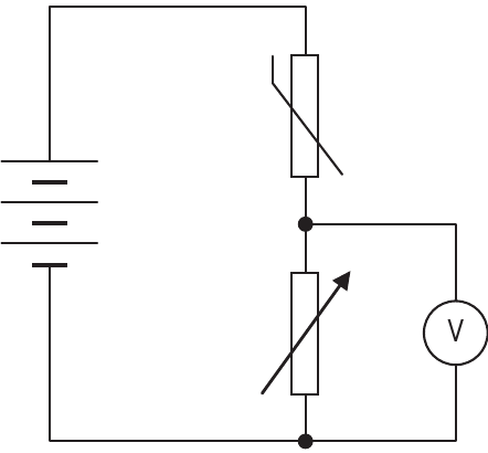
Worked Example: Oven Control Circuit
An oven control circuit where, as temperature increases, the NTC thermistor resistance decreases. This changes , which can trigger a switch to turn off the heating element when the desired temperature is reached.
Temperature rises → NTC resistance decreases → Less voltage across thermistor → changes → Switch triggers → Heating element turns off
Transducers
A transducer is a device that converts one form of energy into another. They can be classified as:
Input transducers
Convert environmental changes into electrical signals:
- LDR: Light energy → Electrical signal
- Thermistor: Heat energy → Electrical signal
- Microphone: Sound energy → Electrical signal
- Strain gauge: Mechanical force → Electrical signal
Output transducers
Convert electrical signals into other forms:
- Buzzer: Electrical energy → Sound energy
- LED: Electrical energy → Light energy
- Motor: Electrical energy → Kinetic energy
- Heater: Electrical energy → Heat energy
Varying switching levels with variable resistors
In practical applications, you often need to adjust the level at which a circuit switches on or off. This is achieved by including a variable resistor in the potential divider circuit.

The switching level can be set:
- By trial and error: Adjust the rheostat until the circuit switches at the desired condition
- Using a scale: Pre-marked settings (e.g., 1-10 on an amplifier volume control, or 150-300°C on an oven)
The variable resistor changes the voltage ratio in the potential divider, allowing fine control of when the output voltage reaches the threshold to trigger the electronic switch.
Technique for analysing potential divider circuits
When analysing circuits containing transducers, follow these steps:
Step 1: Recognise the circuit type
Identify a potential divider circuit - this has a transducer in series with a resistor (or variable resistor) across a voltage source. The circuit may be drawn vertically or horizontally.
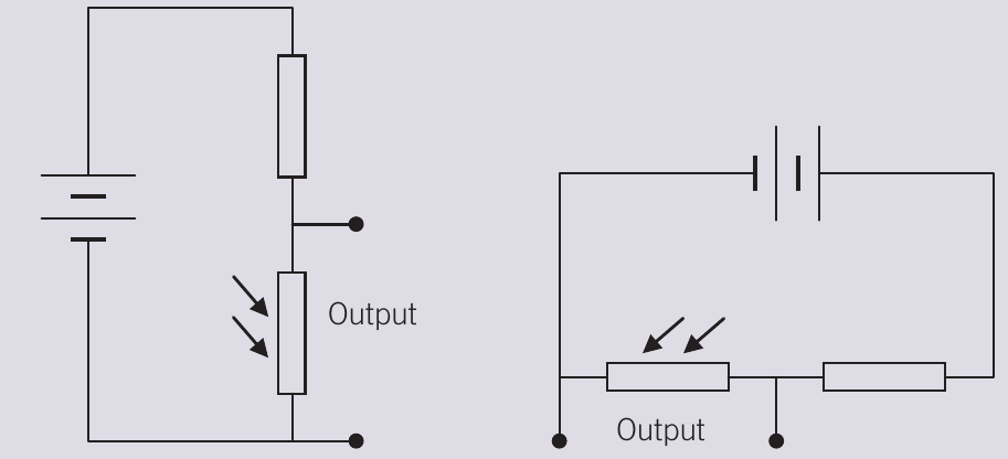
Don't be misled by the shape - look at the connections to understand the circuit.
Step 2: Identify the transducer
Determine which component varies with the environment:
- Thermistor: Responds to temperature
- LDR: Responds to light intensity
- Other transducers: May respond to strain, stress, force, torque, or sound intensity
Step 3: Determine the change
Ask: Will this environmental change increase or decrease the transducer's resistance?
Worked Example: Analysing LDR Resistance Change
If light is getting brighter, an LDR's resistance will decrease (recall the resistance-light graph).
Step 4: Analyse the effect on output
Consider how the resistance change affects . The effect depends on whether the transducer is in the top or bottom position of the potential divider.
Worked Example: LDR in Potential Divider
When an LDR's resistance decreases (brighter light), less of the supply voltage appears across the LDR, so decreases. This decreased voltage might turn off an electronic switch.
Always read the question carefully to understand the complete circuit setup before answering.
Remember!
Key Points to Remember:
-
Diodes allow current flow in only one direction - very low resistance when forward-biased, very high resistance when reverse-biased
-
LEDs are diodes that emit light when forward-biased and are highly efficient light sources for modern applications
-
Potentiometers can function as potential dividers (using three terminals) to vary voltage or as variable resistors/rheostats (using two terminals) to vary current
-
LDRs have high resistance in darkness and low resistance in bright light, making them useful for light-sensing applications like streetlights and security systems
-
Thermistors change resistance with temperature - NTC types (most common) decrease resistance as temperature rises, while PTC types increase resistance with temperature