Networks (AQA A-Level Computer Science): Revision Notes
Networks
Introduction to networks
A network consists of multiple computing devices linked together to enable communication and resource sharing. Networks allow computers to share processing power, storage capacity, and other resources between connected devices. Networks can range from simple setups with just two or three computers in a home or small office to massive global networks like the Internet, which is essentially a worldwide network of networks.
Within a network, each connected device or computer is referred to as a node. These nodes communicate using either physical cables or wireless radio signals to establish connections between them.
Networks can scale from small personal setups to massive global infrastructures. The Internet itself is the largest example, connecting billions of devices worldwide through interconnected networks.
Network basics
Network interface cards
To join a network, a computer requires a network adapter, commonly called a Network Interface Card (NIC). This is a printed circuit board installed inside the computer, similar to graphics cards or sound cards. The NIC is specifically engineered to enable the computer to connect to networks using either wired cables or wireless connections, depending on the network topology being used.
The type of NIC installed determines the maximum speed of data transmission available between that device and the network. Different NICs support different connection standards and speeds, so choosing the appropriate card is important for network performance.
The NIC is a critical component for network connectivity. Without a properly functioning NIC, a device cannot communicate with the network, regardless of how well the rest of the system is configured.
Router functions
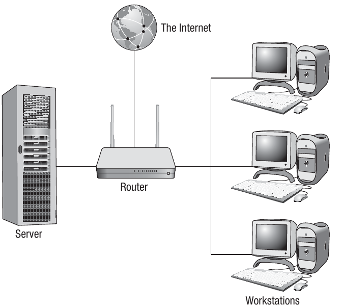
Beyond servers and clients, another essential device in networks is the router. Modern routers combine multiple functions into a single device. A typical home network router performs several important roles:
- Packet forwarding: The router receives each data packet being transmitted, examines the header information, and forwards it to its intended destination
- Firewall protection: Acts as a security barrier, preventing certain packets from being forwarded based on security rules
- Network switching: Creates connections between devices on the network, enabling them to communicate
- Wireless access point: Transmits WiFi signals to provide wireless connectivity
- Modem functionality: Converts digital signals to analogue format so they can be transmitted over standard telephone cables
Network types
Networks are typically categorised by the geographical area they cover and how their connections are configured. This categorisation is known as network topology.
Local area network (LAN)
A Local Area Network (LAN) consists of computers and peripherals connected across a small geographical area, typically confined to a single building or site. LANs are common in businesses, educational institutions, hospitals, and even homes. Most LANs comprise one or more servers alongside multiple client computers.
A server is a high-performance computer with substantial processing power and storage capacity, designed to service numerous users simultaneously. A client refers to any computer connected to the network that accesses services from the server.
The client-server relationship is fundamental to understanding how LANs operate. The server provides resources and services, while clients request and use those resources. This centralized approach makes management and security more efficient.
Wide area network (WAN)
A Wide Area Network (WAN) connects computers and peripherals across a large geographical distance. This could range from networks spanning multiple sites within a region to global networks like the Internet. WANs utilise various communication media beyond simple cables, including telephone wires, microwave links, satellite connections, and fibre optic cables to establish connections over these extended distances.
Network topologies
Star topology
There are two primary topologies (layouts) used in networks today: star and bus. A star topology derives its name from the simplified diagrammatic representation, showing how devices are conceptually connected together.
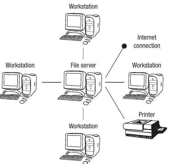
In a star network, each client connects to a central server through an individual, dedicated connection. The key characteristic is this dedicated link between server and client. In practice, a switch occupies the centre position, with the server attached to one of the switch ports. The server will be a high-specification machine with substantial processing power and storage capacity, whilst clients access the server through the cabling infrastructure.
Software can be stored centrally on the server, allowing installation, upgrades, and maintenance to be performed via the server. The server also contains an operating system that manages users' access permissions and includes various administrative functions such as print queue management.
Alternatively, software can be stored locally on individual clients. Local storage reduces start-up time but makes maintenance and upgrades more challenging. Central storage means the administrator maintains much better control over the software and user access permissions.
Understanding Logical vs Physical Layout
It's important to understand that a real star network might not physically resemble the diagram, as clients won't necessarily form a star shape. There will be additional hardware devices such as switches and routers between the server and clients.
However, topology refers to the conceptual or logical layout rather than the actual or physical layout.
Advantages and disadvantages of star topology:
Advantages:
- Fast connection speeds because each client has a dedicated cable
- Network performance remains relatively stable even when many users are online
- Fault-finding is simpler as individual faults are easier to trace
- Relatively secure as the connection from client to server is unique
- New clients can be added without affecting existing clients
- If one cable or client fails, only that specific client is affected
Disadvantages:
- Expensive to set up due to increased cabling costs
- If a cable fails, that particular client may lose data access
- Difficult to install as multiple cables are required, with the problem exacerbated when the LAN spans multiple buildings
- The server can become congested as all communications must pass through it
Bus topology
The other main network topology is the bus topology, where all nodes within the network connect via one main cable. If a main server exists, all clients connect to it through this single main cable, which carries data between the server and clients, with each client branching off the main bus cable.
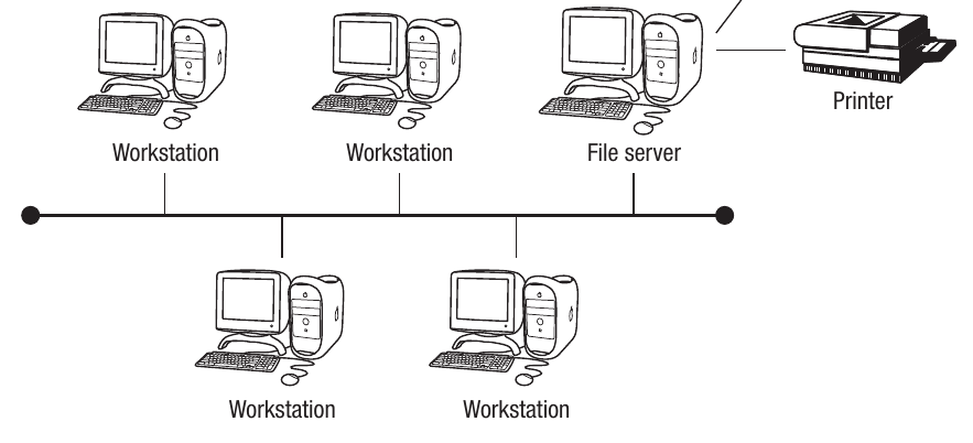
The main cable or backbone must support high-speed data transmission as all data must travel through this single channel. A common implementation uses an Ethernet network system, which has several variants. Ethernet is modelled on the bus network concept, with one central cable carrying all data around the network. Ethernet cards are installed in each client to enable connection using the relevant protocols, with a switch directing data packets to the appropriate client using the address designated for that client.
Ethernet networks are among the most widely used networking technologies. Despite being modeled on the bus topology concept, modern Ethernet implementations often use switches that create a star-like physical topology while maintaining bus-like logical behavior.
Advantages and disadvantages of bus topology:
Advantages:
- Cheaper to install than star topology as only one main cable is required
- Easier to install than star topology
- Easy to add new clients by branching them off the main cable
Disadvantages:
- Less secure than star networks as all data transmits through one main cable
- Transmission speeds decrease when more users join the network
- If the main cable fails, all clients are affected
- Less reliable than star networks due to dependence on the main cable
- More difficult to identify faults
Physical vs logical topology
An important distinction exists between physical topology and logical topology of networks. Physical topology refers to the actual cable connections. However, it's possible for networks physically connected in one topology to operate differently through the addition of hardware and software.
Example: Physical Star, Logical Bus
Some Ethernet networks were physically laid out as stars but used hubs to repeat signals, effectively creating a bus network in operation. This means that while the cables formed a star pattern from a central point, the data transmission behaved as if it were traveling along a single bus, with all devices receiving all transmissions.
Network models
Client-server networks
In both star and bus topologies, diagrams show a main server. Although clients possess local resources in terms of processing power and storage capacity, they are controlled by the server. This means that when new software is installed, it can be installed on the server and then distributed to the clients.
There is a wide range of services that clients may request, including:
- Access to printers
- Secure Internet connection provision
- Email access
- Application access
- File access
This represents the most common method of constructing a LAN with a large number of users. The server must be a high-end computer with substantial processing power and storage capacity, capable of coping with the demands placed upon it by the clients.
Conversely, clients don't need to be such high specifications. Current trends favour thin clients, referring to the fact that the client will lack CD drives or expansion slots, thus reducing client costs.
Thin Clients and Modern Computing
The thin client approach is increasingly popular in modern networks. By relying on the server for most processing and storage, organizations can reduce hardware costs, simplify maintenance, and improve security. Users can work from any thin client terminal while accessing their same environment and files stored on the server.
Peer-to-peer networks
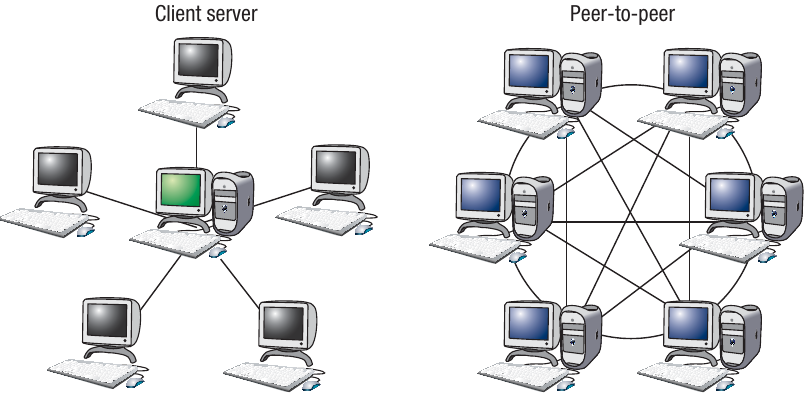
In a peer-to-peer network, no single computer maintains overall control of the network. Instead, the resources of each computer or workstation are available to all computers in the network. Each workstation can therefore function either as a client or as the server, depending on the current task.
This arrangement is more common among smaller networks or for certain applications such as file-sharing. Peer-to-peer networks can be created without requiring a special network operating system. With the growth in home computing, it's increasingly common to find peer-to-peer networks in private houses. These are often configured to allow every computer in the home to share an Internet connection or printer.
Key Difference: Client-Server vs Peer-to-Peer
In client-server networks, there is a clear hierarchy with a powerful central server managing resources. In peer-to-peer networks, all devices are equal partners, sharing resources directly with each other. This makes peer-to-peer more suitable for small networks but less efficient for large-scale operations.
Wireless networks
How wireless networks operate
A wireless network differs from a wired network by not using cables to establish physical connections between devices. Instead, data transmission occurs using radio waves. Wireless networks can be implemented over small or large geographical distances, making it possible to have wireless LANs (WLAN) and Wireless WANs (WWAN). Many business and home networks now operate wirelessly, eliminating the need for costly cabling and enabling easy network access from any device with a wireless network adapter (NIC).
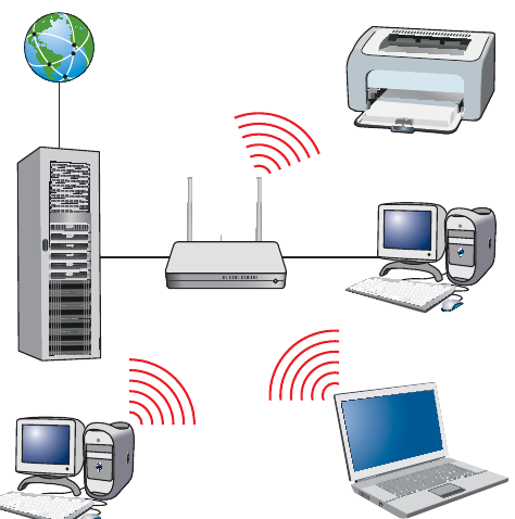
Different communication devices are needed to create wireless networks, depending on geographical coverage. For example, a WLAN in a home or office may have a wireless router that transmits a WiFi signal accessible within a few metres of the device. The 802.11n standard provides coverage of approximately 70m indoors and 250m outdoors (802.11g has slightly less range). WiFi hotspots are established by telecommunication companies and also use wireless routers to provide access over larger distances of around 250 metres. These may be slower because the signal degrades with distance and there will be more users sharing the same signal, potentially causing interference.
WWANs typically utilise mobile phone networks, which in turn use satellites and transmitters and receivers located on towers around the country. These are capable of transmitting signals over long distances using set frequencies.
Media Access Control (MAC) addresses
All devices on a network have what is called a Media Access Control (MAC) address. This is a unique identifier encoded into the network interface card (NIC) in the format of six groups of two hexadecimal digits separated by colons, e.g. 01:23:45:67:89
. Any device connecting to a network using WiFi will connect through a wireless access point and must have its own unique MAC address.Every NIC ever manufactured has a unique address, meaning they can be used to identify every device uniquely. The first half of the MAC address is the manufacturer code, and the second half is the unique device code allocated by that manufacturer.
Understanding MAC Address Format
A MAC address consists of 12 hexadecimal digits (0-9 and A-F) organized into six pairs. For example, in the address 01:23:45:67:89
:- The first three pairs (01:23:45) identify the manufacturer
- The last three pairs (67:89) uniquely identify the specific device
This ensures that no two network devices anywhere in the world have the same MAC address.
WiFi and WLAN
WiFi is the generic term for a Wireless Local Area Network (WLAN) where devices can connect wirelessly to each other and where a connection can be made to the Internet, providing one of the devices in the network is online. WiFi operates to a generic standard called IEEE 802.11, ensuring that all devices are compliant and can connect and transmit data around the network.
Wireless protocols
Sets of standards or protocols exist for wireless communications to ensure that all devices connecting to WiFi can connect with each other and transmit and receive data. A protocol called Carrier Sense Multiple Access with Collision Avoidance (CSMA/CA) was developed to enable various devices to transmit data at high speeds without interfering with each other.
When data are sent around networks, they are transmitted in frames, with all frames being re-assembled at the receiving end. Any device on a wireless network may attempt to send frames. These data frames can be picked up by any nodes or devices within range. Before each frame is sent, the device uses the CSMA/CA protocol to determine whether the transmission medium is idle or whether another device is using it. If the transmission medium is idle, the data are sent. If it is busy, the device will wait and try again later. Each device will then wait a random amount of time before checking to see if the medium is free again so that it can send the data. This is known as a back-off mechanism and is random to reduce the chances of both devices trying to send simultaneously again.
How CSMA/CA Prevents Collisions
The CSMA/CA protocol is essential for wireless networks because multiple devices share the same transmission medium (radio waves). By checking if the medium is free before transmitting and using random wait times, the protocol minimizes the risk of two devices transmitting simultaneously and causing data collisions.
RTS/CTS protocol
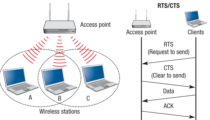
If the transmission medium is free, then the data can be sent. On receipt of the data, an acknowledgement is sent back to the sending device to confirm that the data have been received and not corrupted. If this is not received, again it will wait a random amount of time before resending.
An optional extension to the protocol is a system called Request to Send/Clear to Send (RTS/CTS), which works between the nodes on a network. The RTS sends a message to the receiving node or access point, and if a CTS message is received, it knows that the node is idle and that the data frame can be sent. If no CTS message is received, it will wait and send another RTS later.
Service Set Identifier (SSID)
One of the issues when using wireless networks is ensuring that various devices are connecting to the correct WLAN. As all data are being sent through radio waves rather than cables, each device needs a way of ensuring that it is connecting to the correct network. The standard method of doing this is using a Service Set Identifier (SSID), which is a 32-character code put into the header of each packet of data being sent.
Each code is locally unique to the particular WLAN being used and therefore acts as an identifier allowing that frame of data to be transmitted around the WLAN. The network interface card must also be programmed with the same 32-character code so that the device can connect to the WLAN in the first place.
SSID Security Considerations
While the SSID helps devices identify and connect to the correct network, it should not be considered a security feature on its own. SSIDs can be easily detected by anyone with wireless scanning tools. For true security, you must use encryption protocols like WPA/WPA2 in addition to the SSID.
Network security
Security issues with wireless networks
Another issue with wireless technology is that it can be less secure than a wired system. This is because the signals travel through the air and are therefore easier to intercept than signals passing through wires. A potential hacker can tap into the radio signal being sent using receiving devices and read the data signals. There are several steps that can be taken to increase the level of security on a wireless network:
- Change the SSID from the default value and hide it from transmission
- Ensure that all devices are WiFi Protected Access (WPA/WPA2) compliant
- Use strong encryption (WPA/WPA2)
- Create a 'white list' of MAC addresses from devices that you know to be trustworthy
By implementing these security measures, wireless networks can be made significantly more secure against unauthorised access and data interception.
Critical Security Practices
Never leave your wireless network with default settings. Many routers come with standard SSIDs like "NETGEAR" or "Linksys" and default passwords that are well-known to hackers. Always change these immediately upon installation and enable the strongest encryption available (preferably WPA2 or WPA3).
Key Points to Remember:
-
Networks connect multiple devices to share resources, data, and processing power. Each connected device is called a node, and devices connect via cables or wireless signals.
-
Network topology describes the layout: Star topology has dedicated connections from each client to a central server/switch, whilst bus topology uses one main cable to which all devices connect. Topology refers to the logical layout, not necessarily the physical arrangement.
-
Client-server networks have a powerful central server providing resources and services to multiple clients, whilst peer-to-peer networks allow all devices to share resources equally without a central server.
-
Wireless networks use radio waves instead of cables and require each device to have a unique MAC address for identification. WiFi operates on the IEEE 802.11 standard to ensure all devices can communicate.
-
Security protocols are essential for wireless networks: CSMA/CA prevents data collisions, RTS/CTS manages transmission rights, SSID identifies the network, and WPA/WPA2 encryption protects data from unauthorised access.