Refraction at a plane surface (AQA A-Level Physics): Revision Notes
3.2.3 Refraction at a plane surface
Refractive Index
The refractive index of a material measures how much it slows down light as it travels through the material. It is calculated as:
Where:
- is the speed of light in a vacuum,
- is the speed of light in the material. A higher refractive index indicates that the material is more optically dense, meaning it slows down light more. For example, the refractive index of air is approximately 1, indicating it has little effect on light speed compared to a vacuum.
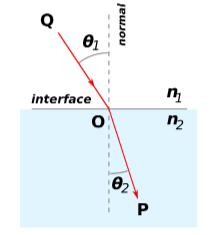
Refraction and Snell's Law
Refraction occurs when a wave enters a new medium and its speed changes, causing it to change direction. Light bends towards the normal if it slows down (entering a more optically dense medium) and away from the normal if it speeds up (entering a less optically dense medium).
Snell's Law describes the relationship between the angles of incidence and refraction:
where:
- and are the refractive indices of the first and second materials,
- is the angle of incidence in the first material,
- is the angle of refraction in the second material.
Example: If light travels from air (refractive index ) into glass (refractive index ), it will bend towards the normal as it slows down due to the higher optical density of glass.
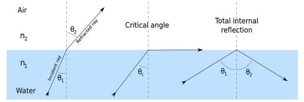
Critical Angle and Total Internal Reflection
When light travels from a more to a less optically dense medium (e.g., glass to air), it can experience total internal reflexion () if the angle of incidence exceeds a certain critical angle .
- Critical Angle:
where , with being the refractive index of the denser medium.
- Total Internal Reflexion ():
- Occurs when the angle of incidence is greater than the critical angle, causing all the light to reflect back into the denser medium.
- This phenomenon is used in optical fibres and other applications where light needs to be contained within a material.
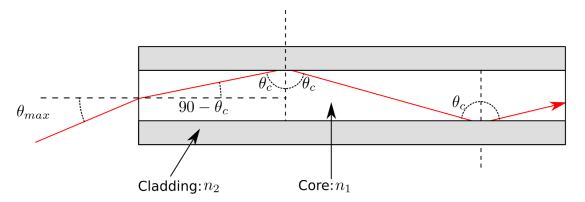
Applications of TIR: Optical Fibres
Optical fibres use TIR to transmit light signals over long distances with minimal loss. An optical fibre consists of:
- Core: Made of optically dense material with a higher refractive index.
- Cladding: Surrounds the core with a lower refractive index, enabling TIR within the core. This structure keeps light signals inside the core, allowing efficient data transmission.
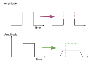
Challenges with Signal Transmission in Optical Fibres:
- Absorption: Some energy is absorbed by the fibre, reducing signal amplitude.
- Dispersion: Causes pulse broadening, where the signal spreads out over time, potentially leading to information loss.
Types of Dispersion
- Modal Dispersion:
- Caused by different light paths in the fibre, as light enters at various angles.
- Can be reduced by using narrower cores.
- Material Dispersion:
- Caused by different wavelengths of light travelling at different speeds in the fibre.
- Reduced by using monochromatic light. Signal Regeneration: An optical fibre repeater can be used to regenerate the signal, reducing the effects of absorption and dispersion over long distances.
Key Points
- Refractive Index: Measures how much a material slows down light.
- Refraction: Change in wave direction when entering a new medium, calculated by Snell's Law.
- Critical Angle and TIR: Total internal reflexion occurs when light meets the critical angle; used in optical fibres.
- Optical Fibres: Use TIR for efficient data transmission, but are affected by absorption and dispersion.