Creating Boolean Expressions from Logic Circuits (AQA GCSE Computer Science): Revision Notes
Creating Boolean expressions from logic circuits
What is it?
Creating Boolean expressions from logic circuits is the process of writing a mathematical statement that describes what a digital circuit does. When you look at a logic circuit diagram with different gates connected together, you need to trace the signal flow and translate it into a Boolean expression using AND, OR, and NOT operations.
This skill is essential because it helps you understand exactly what a circuit will output for any given set of inputs, and it's the reverse process of drawing circuits from Boolean expressions.
The step-by-step process
When you're given a logic circuit diagram, follow these steps to create the Boolean expression:
- Identify all the logic gates in the circuit (AND, OR, NOT gates)
- Trace the signal path from inputs to output, working left to right through the circuit
- Use brackets to show which operations happen first (just like in maths)
- Write the expression using the correct Boolean operators
The key is to work through each gate in the order that the signals would flow through them, making sure to use brackets to show the correct order of operations.
Worked examples
Worked Example 1: Combining OR and AND operations
Let's look at this circuit step by step. We can see there's an OR gate feeding into a NOT gate, and then that result goes into another OR gate along with input C.
Here's how to work through it:
- First, inputs A and B go into an OR gate, giving us: (A OR B)
- Next, this result passes through a NOT gate, giving us: NOT (A OR B)
- Finally, this connects with input C through another OR gate for the final output
So our complete Boolean expression is:
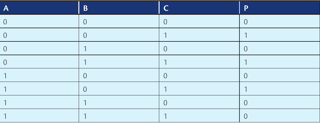
The truth table confirms our expression is correct, showing all possible input combinations and their corresponding outputs.
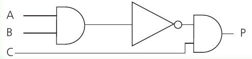
Worked Example 2: OR gate with inverted input
In this circuit, input A connects directly to an OR gate, but input B first passes through a NOT gate before reaching the same OR gate. When we trace through this:
- Input A goes directly to the OR gate
- Input B is inverted (NOT B) before reaching the OR gate
- The OR gate combines these: A OR (NOT B)
Therefore, the Boolean expression is:
Understanding brackets in Boolean expressions
Brackets are crucial in Boolean expressions because they show which operations happen first, just like in regular maths. When you see a circuit where the output of one gate becomes the input to another gate, you need brackets to show this relationship clearly.
For example:
- means: first calculate A OR B, then AND the result with C
- means: first calculate B AND C, then OR the result with A
Real-world applications
Practical Example: Family Holiday Planning
Boolean logic isn't just theoretical - it's used in real decision-making systems. For instance, imagine a family planning a holiday with these conditions:
- They have a budget of £2,000 maximum (A)
- They want a holiday with a pool (B)
- They'd prefer to go to the USA (C)
The family will be happy if they stay within budget AND either find a place with a pool OR can go to the USA. This gives us the Boolean expression:
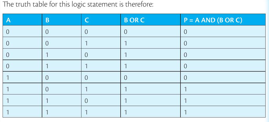
This truth table shows all possible combinations and when the family would be satisfied with their holiday choice.
Exam tips
Essential Exam Strategies:
- Always work left to right through the circuit, following the signal flow
- Use brackets to group operations that happen at the same gate
- Double-check your expression by testing it with a few input combinations
- Remember that NOT gates are represented by small circles on the circuit diagrams
- Draw intermediate steps if the circuit is complex - it helps avoid mistakes
Key Points to Remember:
- Trace the signal flow from left to right through each gate in the circuit
- Use brackets to show which operations happen first, just like in maths
- NOT gates are shown by small circles on the output of gates or triangular symbols with circles
- Check your work by creating a truth table to verify your Boolean expression matches the expected outputs
- Practice makes perfect - the more circuits you convert, the easier it becomes to spot the patterns