Logic Circuits and Truth Tables (AQA GCSE Computer Science): Revision Notes
Logic circuits and truth tables
When you understand individual logic gates, the next step is learning how to combine them to create more complex circuits. This is where things get really exciting because you can build circuits that make decisions and solve problems!
What are combined logic circuits?
A combined logic circuit uses two or more logic gates connected together. The output from one gate becomes the input to another gate, creating a chain of logical operations. Think of it like a factory assembly line - each gate does its job and passes the result to the next gate.
The assembly line analogy is particularly helpful here - just like workers on a production line, each gate has a specific job and passes its result to the next stage in the process.
These combined circuits are everywhere in computers, from simple calculators to complex processors. Learning how they work helps you understand how computers make decisions and process information.
The XOR gate as a building block
Before we dive into combinations, let's make sure you understand the XOR gate, as it appears in many combined circuits. An XOR (Exclusive OR) gate is quite special - it only outputs 1 when exactly one of its inputs is 1, but not both.

The key thing to remember about XOR is that it wants "either A or B, but not both". This makes it useful for detecting differences between inputs.
Combining AND and NOT gates
One of the simplest combinations connects a NOT gate to the output of an AND gate. This creates what's called a NAND gate (NOT AND).
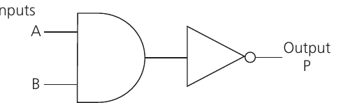
Step-by-Step: How NAND Works
- First, the AND gate processes inputs A and B
- The result (let's call it R) goes to the NOT gate
- The NOT gate flips the result to give us the final output P
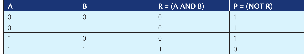
The Boolean expression for this circuit is: P = NOT (A AND B)
This type of combination is particularly useful because NAND gates can actually be used to build any other type of logic gate - they're universal building blocks!
Combining AND and OR gates with three inputs
Now let's look at a more complex example with three inputs. This circuit first performs an AND operation on two inputs, then feeds that result into an OR gate along with a third input.
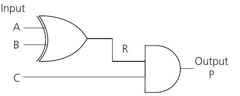
The Boolean expression becomes: P = (A AND B) OR C
Building the truth table step by step
When you have three inputs, your truth table needs more rows. Here's the key rule: for n inputs, you need 2^n rows. So for 3 inputs: rows.
Building a 3-Input Truth Table
Start by listing all possible combinations of your three inputs A, B, and C:
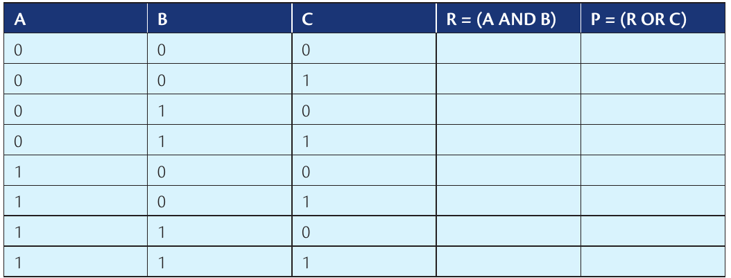
Next, work out the intermediate result R = (A AND B) for each row:
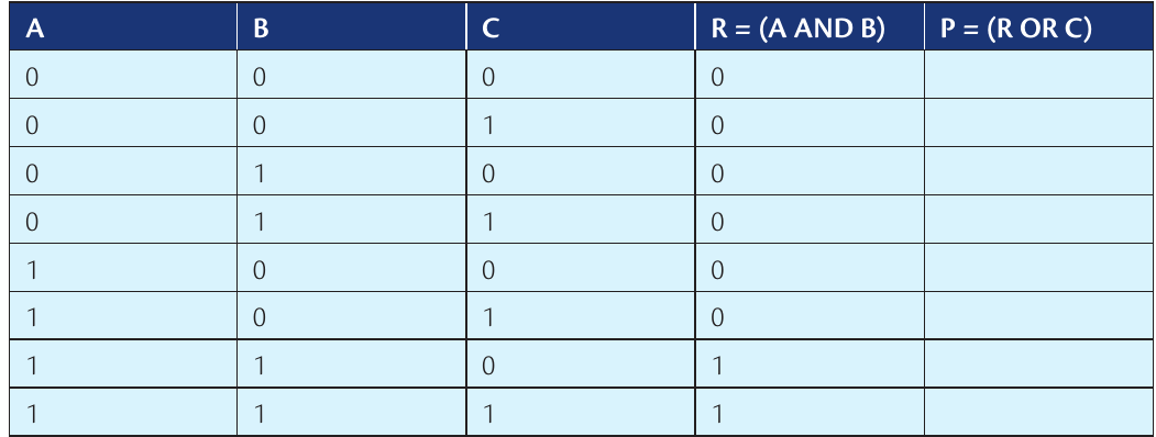
Finally, calculate the final output P = (R OR C):
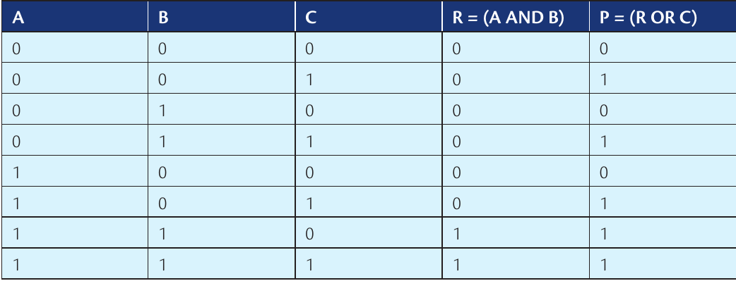
The systematic approach is crucial here. Work through each gate in order, just like the circuit would process the signals.
Combining XOR and AND gates
Another common combination uses an XOR gate feeding into an AND gate. This creates interesting behaviour that's useful in many digital systems.
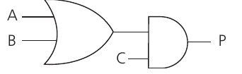
Wait, that's not quite right for our example. Let me show you the XOR and AND combination we're focusing on:
XOR and AND Circuit Operation
The circuit works like this:
- XOR gate processes inputs A and B to produce R
- AND gate takes R and input C to produce final output P
The Boolean expression is: P = (A XOR B) AND C
Let's build this truth table systematically:
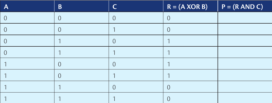
Notice how this circuit only outputs 1 when C is 1 AND exactly one of A or B is 1 (but not both). This type of logic is useful for conditional operations.
Key strategies for truth tables
Here are some essential tips for working with combined logic circuits:
Counting rows correctly: Always use the formula 2^n where n is the number of inputs. Double-check by counting in binary: for 3 inputs you get 000, 001, 010, 011, 100, 101, 110, 111.
Work step by step: Don't try to jump straight to the final answer. Calculate each intermediate result first, just like the circuit would.
Check your logic: Make sure each gate follows its rules:
- AND needs ALL inputs to be 1
- OR needs AT LEAST ONE input to be 1
- XOR needs EXACTLY ONE input to be 1
- NOT flips whatever it receives
Draw it out: If you're struggling, sketch the circuit and trace through each signal path.
Reading Boolean expressions
When you see expressions like P = (A XOR B) AND C, read them from the inside out:
- First, A XOR B happens
- Then, the result gets AND-ed with C
- This gives you P
Order of Operations in Boolean Logic
The brackets show you the order of operations, just like in maths. Without brackets, you follow the standard order: NOT first, then AND, then OR, then XOR.
Real-world applications
These combined circuits aren't just academic exercises - they're the building blocks of:
- Calculators: Adding, subtracting, and comparing numbers
- Security systems: Checking multiple conditions before allowing access
- Traffic lights: Managing complex timing and sensor inputs
- Game controllers: Processing multiple button presses simultaneously
Understanding how to combine simple gates gives you insight into how all these systems work under the hood.
Key Points to Remember:
- Truth tables for n inputs always have 2^n rows - this helps you avoid missing any combinations
- Work through circuits step by step - calculate intermediate results before the final output
- XOR gates output 1 when inputs are different, AND gates need all inputs to be 1, OR gates need at least one input to be 1
- Boolean expressions follow order of operations - brackets first, then NOT, AND, OR, XOR
- Combined circuits are everywhere in computing - from simple calculators to complex processors