Communication of design ideas (AQA GCSE Design and Technology): Revision Notes
Communication of design ideas
Communication is essential in design and technology. As a designer, you need to share your ideas clearly with others, whether they're clients, manufacturers, or fellow designers. There are many different techniques available, each with specific purposes and advantages.
The ability to communicate design ideas effectively determines whether your concepts will be understood, approved, and successfully manufactured. Different communication methods serve different stages of the design process.
Freehand sketching
Sketching serves as a quick and convenient method for recording your initial thoughts and sharing them with others. This fundamental skill allows you to capture ideas as they develop and communicate concepts before moving to more detailed drawings.
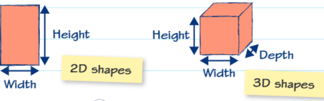
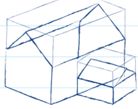
When sketching, always use a suitable pencil such as HB grade. Start by deciding whether you need a 2D or 3D representation, then use light, loose lines initially. The crating technique helps create a framework for your drawing - imagine your object sitting inside a transparent box, then draw the outline of this box first before adding the object details inside.
Common Sketching Mistakes to Avoid:
- Using too hard a pencil (2H, 3H) which creates faint, difficult-to-see lines
- Starting with dark, heavy lines that cannot be easily modified
- Focusing on details before establishing basic proportions and overall shape
 Once you're satisfied with the basic proportions, you can go back and add more detail, making your final lines darker and more definite. Remember that sketching is about communication, not perfection.
Technical drawing methods
Orthographic drawings
Orthographic drawings present objects in two dimensions and represent one of the most precise ways to communicate design information. These drawings show different views of an object arranged in a specific, standardised layout.
The most common form is called third angle projection, which arranges the plan view (looking down from above), front view, and end view in a precise order. This systematic approach ensures anyone reading your drawing understands exactly what they're looking at.
 When creating orthographic drawings, you often need to convert your initial 3D sketches into these flat, precise views. Sometimes a second end view might be added to the left side if additional clarity is needed.
All technical drawings benefit greatly from dimensions - measurements that show the exact size of features. This allows products to be visualised accurately and constructed from the drawing.
Worked Example: Scale Calculation
If a drawing uses a scale of 4:1, this means each line drawn will be four times larger than the actual full-scale measurement.
Problem: A component measures 20mm in real life. How long should it be drawn at 4:1 scale? Solution: 20mm × 4 = 80mm on the drawing
Problem: A line on a 4:1 scale drawing measures 60mm. What is the real-life measurement? Solution: 60mm ÷ 4 = 15mm in real life
Isometric projection
This technique represents three-dimensional shapes while maintaining actual size relationships. In isometric projection, all dimensions remain true to scale, vertical lines stay vertical, and horizontal lines are drawn at 30 degrees to the horizontal.
 The beauty of isometric projection lies in its combination of visual clarity and dimensional accuracy. Unlike perspective drawings, measurements can be taken directly from an isometric drawing, making it valuable for both communication and construction purposes.
Isometric projection is particularly useful in technical fields because it maintains proportional relationships while still providing a three-dimensional appearance that's easy to understand.
Perspective drawing
Perspective techniques create more realistic representations of three-dimensional objects by mimicking how our eyes actually see things.
One point perspective works by drawing the front face of your object, then extending lines back to a single vanishing point (VP). The vanishing point typically sits on the horizon line, representing your eye level when looking at the object.
Two point perspective creates even more realistic results by using two vanishing points. The sides of the object extend to these two separate points, creating a more natural, photographic appearance.
Key Difference: One point perspective is ideal for objects viewed straight-on, while two point perspective is better for objects viewed from an angle, creating more dynamic and realistic representations.
Detailed communication methods
Annotated drawings
These drawings combine visual representation with detailed written information. Annotations provide specific details about materials, dimensions, manufacturing processes, and design features that wouldn't be clear from the drawing alone.
For example, an annotated chair design might include information about the wood type, joint construction methods, angle measurements for comfort, dimensions, and surface treatments. This comprehensive approach ensures nothing is left to guesswork.
Annotations bridge the gap between what can be shown visually and what must be communicated through text. They're essential for manufacturing specifications and quality control.
System diagrams
System diagrams excel at showing how things work rather than what they look like. They use input, process, and output boxes connected by arrows, often including feedback loops to show how systems respond and adjust.
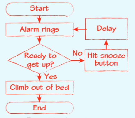 These diagrams prove particularly useful for electronic systems, breaking down complex operations into understandable stages. For instance, a heating system diagram would show temperature input, processing decisions, and outputs like turning boilers on or off, with feedback loops monitoring the results.
Schematic diagrams
Rather than showing what components look like, schematic diagrams use standardised graphic symbols to represent system elements. This approach creates clear, unambiguous diagrams that anyone familiar with the symbols can understand immediately.
Electrical circuits provide the most common example - instead of drawing detailed pictures of batteries, switches, and lamps, simple symbols represent each component. This makes complex circuits much easier to read and understand.
Exploded drawings
These specialised drawings show how assemblies fit together by separating all individual parts while maintaining their relative positions. Each component appears in its correct location but pulled apart from the others, revealing construction details and assembly sequences.
Exploded drawings prove invaluable for showing information about joints, adhesives, fixings, and materials that would be hidden in a normal assembled view.
Modern communication methods
Computer aided design (CAD)
CAD software has revolutionised design communication by offering several significant advantages. It reduces human error, allows precise zooming into specific details, makes saving and editing much easier, and works much faster than hand drawing.
CAD systems can generate accurate technical drawings from 3D models, automatically maintain consistency across different views, and easily incorporate changes throughout a design.
Key CAD Advantages:
- Automatic generation of multiple views from a single 3D model
- Instant updates across all views when changes are made
- Precise measurements and dimensioning tools
- Easy file sharing and collaboration capabilities
3D modelling
Three-dimensional computer models allow designers to create scale versions of their designs for testing different aspects before committing to full production. These models can be rotated, sectioned, and analysed in ways impossible with traditional drawings.
Audio and visual recordings
Modern technology enables designers to document interviews for research purposes or show clients work progress through video recordings. These methods capture information that static drawings cannot convey, such as movement, user interactions, or manufacturing processes.
Key Points to Remember:
- Freehand sketching is your quickest way to capture and share initial design ideas - use light lines and crating techniques for better results
- Orthographic drawings provide the most precise way to show exact dimensions and details using standardised third angle projection
- Isometric projection combines 3D visual clarity with accurate measurements, making objects easy to understand and build
- Annotated drawings add essential written details about materials, processes, and specifications that visual information alone cannot convey
- Modern CAD and 3D modelling tools offer speed, accuracy, and flexibility that traditional methods cannot match