Electric Current (Junior Cert Engineering): Revision Notes
Electric Current
What is electric current?
Electric current is the flow of electrons through a conductor. To understand this, we need to look at the basic structure of atoms.

Matter is made up of tiny particles called atoms. Each atom has a central nucleus containing protons (positive charge) and neutrons (no charge), with electrons (negative charge) orbiting around it. In metals, some outer electrons are free to move around randomly through the atomic structure.
In metallic conductors, the outer electrons of atoms are not tightly bound to their parent atoms. These "free electrons" can move randomly through the metal's crystal lattice structure, creating a "sea of electrons" that makes electrical conduction possible.
When a piece of metal becomes part of an electrical circuit (like connecting it to a battery), these free electrons start flowing in a definite direction. This organised movement of electrons is what we call electric current.
The electrons actually flow from the negative terminal of a battery to the positive terminal. However, before scientists discovered electrons, they thought current flowed from positive to negative. This idea has been kept as conventional current direction, even though we now know electrons flow the opposite way.
Understanding Current Direction
While electrons flow from negative to positive (electron flow), we still use the historical convention that current flows from positive to negative (conventional current). This conventional direction is used in all circuit analysis and electrical calculations, so it's essential to remember this standard approach.
Conductors and insulators
Materials behave differently when it comes to allowing electric current to flow through them:
Conductors are materials that allow current to flow freely through them. Metals are excellent conductors because they have lots of free electrons that can move easily.
Insulators are materials that do not allow current to flow through them. Examples include:
- PVC (plastic)
- Acrylic (perspex)
- Phenol formaldehyde (Bakelite)
- Wood
- Mica
- Rubber
These materials are used to cover electrical wires and make electrical equipment safe to handle.
Why Metals Conduct
Metals have a unique atomic structure where outer electrons are shared among all atoms in a "sea of electrons." This allows electrons to move freely when voltage is applied. In contrast, insulators have electrons tightly bound to their atoms, preventing current flow.
Power sources
To make electrons flow and create current, we need electrical "pressure" called electromotive force (e.m.f.). This is measured in volts (V).
Batteries are common power sources made from cells joined together. For example:
- A carbon/zinc cell gives 1.5V
- A 4.5V battery contains three 1.5V cells connected together
Batteries supply direct current (DC), which means the current flows in the same direction all the time.
The electricity supply in Ireland provides alternating current (AC). This current changes direction 50 times per second (50 Hz) at 220V. For school work, we use special low voltage power supplies that reduce mains voltage to safer levels of 0-25V.
Safety with Electrical Supplies
Always use low voltage supplies (0-25V) for school experiments. Mains voltage (220V AC) is dangerous and should never be used directly in educational settings. The high frequency of AC (50 Hz) means the current direction changes 100 times per second.
Ohm's law and electrical relationships
Three important electrical quantities are linked by Ohm's law:
- Voltage (V) - measured in volts - the electrical "pressure"
- Current (I) - measured in amperes or amps - the flow of electrons
- Resistance (R) - measured in ohms (Ω) - how much a material opposes current flow
Ohm's law states: V = I × R
This can also be rearranged as:
- I = V ÷ R (to find current)
- R = V ÷ I (to find resistance)
A helpful way to remember this is using a triangle - cover the quantity you want to find and what's left visible gives you the calculation:
The Ohm's Law Triangle
The triangle shows V at the top, with I and R at the bottom. If you want to find voltage, cover V and you see I × R. If you want current, cover I and you see V ÷ R. If you want resistance, cover R and you see V ÷ I.
Worked Example: Using Ohm's Law
If the voltage across a conductor is 6V and the current flowing through it is 3 amps, what is its resistance?
Step 1: Identify the known values
- Voltage (V) = 6V
- Current (I) = 3A
- Resistance (R) = ?
Step 2: Apply Ohm's law formula R = V ÷ I
Step 3: Substitute the values R = 6 ÷ 3 = 2Ω
Measuring electrical quantities
Measuring current
Ammeters measure electric current. The units commonly used are:
- Ampere (A)
- Milliamp (mA) = 1/1000 amp
- Microamp (μA) = 1/1,000,000 amp
Ammeter Connection Rules
An ammeter must be connected in series (directly into the circuit path). The positive terminal connects to the positive side of the circuit, and negative to negative. Always use the correct range to avoid damaging the metre.
Measuring voltage
Voltmeters measure voltage (potential difference) between two points in a circuit, such as across a lamp or battery.
Voltmeter Connection Rules
A voltmeter must be connected in parallel with the component being measured. It measures the "electrical pressure" between two points and should never be connected in series as this would prevent current flow.
Using multimeters

A multimeter is a versatile instrument that can measure current, voltage, and resistance. It can be digital or analogue (with a moving pointer).
To measure resistance:
- Select the resistance (ohms) range
- Check and adjust the zero mark if needed
- Connect the probes to the component
- Read the scale from right to left (zero on right, infinite resistance on left)
Continuity Testing
Continuity testing uses an ohmmeter to check if a circuit or component has a complete path for current:
- Very low resistance = good connection
- Very high resistance = break in circuit
This is essential for troubleshooting electrical problems and ensuring safe connections.
Series and parallel circuits
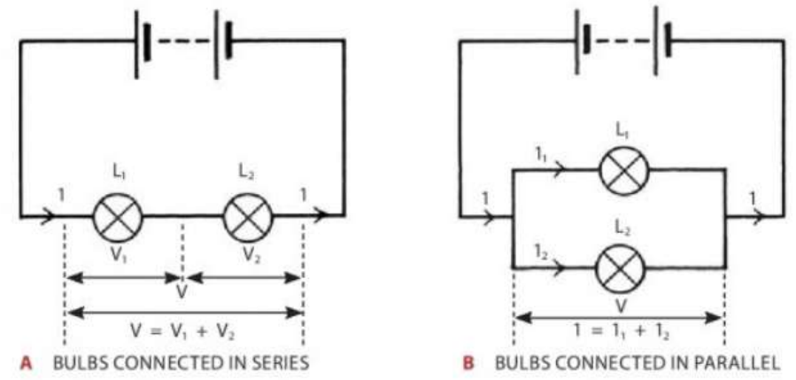
Series circuits
In a series circuit, components are connected end-to-end in a single loop:
- Current is the same through all components:
- Voltage divides between components:
- If one component fails, the whole circuit stops working
Parallel circuits
In a parallel circuit, components are connected in separate branches:
- Voltage across each branch is the same:
- Current divides between branches:
- If one component fails, others continue working
Practical Implications
Series circuits are like old Christmas lights - if one bulb burns out, they all go off. Parallel circuits are like household lighting - each light has its own switch and operates independently. This is why parallel circuits are preferred for most electrical installations.
Simple circuit applications
Basic torch circuit
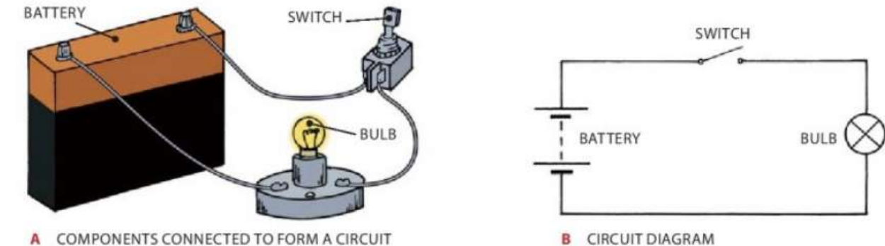
A simple circuit consists of:
- Battery (power source)
- Switch (to control current flow)
- Bulb (converts electrical energy to light)
When the switch closes, it completes the circuit allowing current to flow and the bulb lights up. When open, the circuit is broken and current stops.
Practical applications
Dexterity game
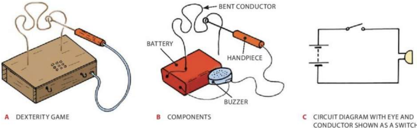
This steady-hand game uses a simple circuit with a battery, buzzer, and two conductors. When the metal loop touches the bent wire, it completes the circuit and the buzzer sounds.
Circuit Completion Principle
The dexterity game demonstrates how any break in a circuit prevents current flow. When the loop touches the wire, it provides the missing connection needed to complete the electrical path.
Bicycle dynamo lighting
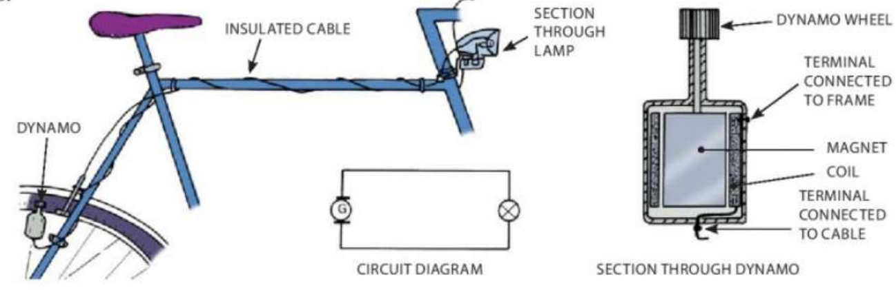
A dynamo generates electricity when the bicycle wheel turns. It contains a magnet and coil - as the wheel spins, it rotates the magnet, creating current to power the headlight.
Energy Conversion
The bicycle dynamo converts mechanical energy (wheel rotation) into electrical energy through electromagnetic induction. This demonstrates how different forms of energy can be transformed to create useful electrical power.
Safety components
Filament bulbs

Traditional light bulbs work by heating a thin tungsten wire (filament) until it glows. The bulb contains inert gases to prevent the filament from burning out quickly.
Fuses and circuit breakers
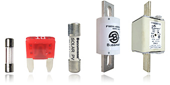
Fuses are safety devices that protect circuits from too much current:
- They contain a thin wire that melts if current gets too high
- Different types include ceramic cartridge, glass cartridge, and plug fuses
- Common ratings are 3A, 6A, 10A, 13A
Circuit breakers do the same job as fuses but can be reset after they trip, rather than needing replacement.
Critical Safety Points
- Always use the correct fuse rating
- Fuses must be fitted in the "live" side of a circuit
- They protect equipment but cannot prevent electric shock
- Never replace a fuse with wire or incorrect rating
Incorrect fuse ratings can lead to fires, equipment damage, or failure to protect when needed.
Circuit symbols
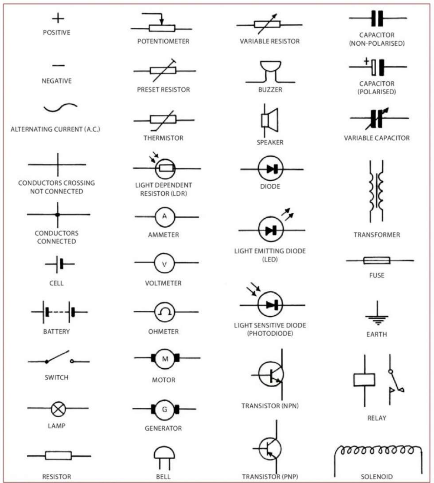
Engineers use standard symbols to draw circuit diagrams. Key symbols include:
- Battery: parallel lines with + and - signs
- Switch: gap with connecting line
- Lamp: circle with X inside
- Resistor: rectangular box
- Ammeter: circle with A
- Voltmeter: circle with V
- Fuse: rectangular box
- Motor: circle with M
- Bell/buzzer: dome shape
Importance of Standard Symbols
Learning these symbols is essential for reading and drawing electrical circuits. They provide a universal language that allows engineers and technicians worldwide to understand circuit designs regardless of their spoken language.
Key Points to Remember:
- Electric current is the flow of electrons from negative to positive terminals in a circuit
- Conductors (like metals) allow current flow easily, while insulators (like plastic) prevent current flow
- Ohm's law: - voltage equals current times resistance
- Ammeters connect in series to measure current, voltmeters connect in parallel to measure voltage
- In series circuits current is the same throughout, in parallel circuits voltage is the same across branches
- Fuses and circuit breakers protect circuits by cutting off excessive current flow
- Always use proper safety procedures when working with electricity, especially avoiding mains voltage in school work