Circuits (Junior Cert Engineering): Revision Notes
Circuits
Understanding potential dividers
A potential divider is a simple but important circuit that allows you to split a supply voltage into smaller, useful voltages. This technique is essential for controlling electronic components like transistors.
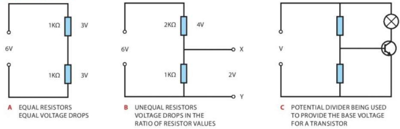
When two resistors are connected in series across a voltage supply, they share the total voltage between them. The voltage drop across each resistor depends on its resistance value:
- Equal resistors create equal voltage drops - if you have two 1kΩ resistors across 6V, each will drop 3V
- Unequal resistors create voltage drops in proportion to their resistance values - a 2kΩ resistor will drop twice as much voltage as a 1kΩ resistor in the same circuit
- Variable resistors (potentiometers) allow you to adjust the voltage division by changing the resistance ratio
Critical Design Rule
When you connect a load to a potential divider, the load resistance should be at least ten times greater than the divider resistor value. This prevents the load from significantly affecting the voltage division.
Circuit design process
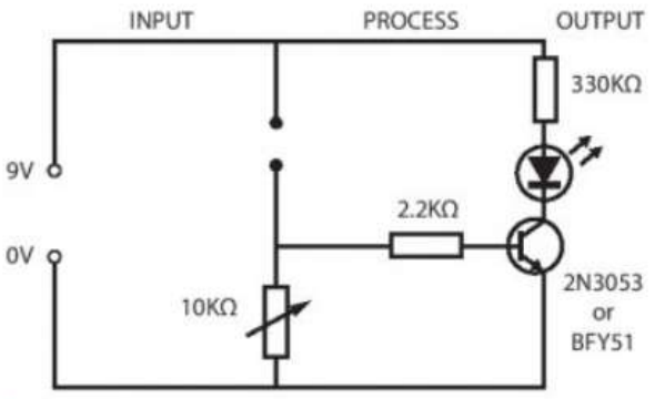
Electronic circuits can be understood using a systematic approach called the input-process-output model. This breaks any circuit into three main parts:
- Input: Sensors that detect changes in the environment (temperature, light, moisture)
- Process: Components that respond to input changes, usually involving a switching device like a transistor
- Output: Devices that produce the desired result (buzzers, lights, LEDs)
Practical Example: Home Security System
Input: Door sensor detects when opened Process: Transistor circuit processes the sensor signal Output: Alarm buzzer activates to alert occupants
This systematic approach helps ensure you consider all aspects of your circuit design.
Temperature sensing circuits
Temperature-activated circuits use a thermistor as the input sensor. A thermistor's resistance decreases as temperature increases, which changes the voltage in a potential divider circuit.
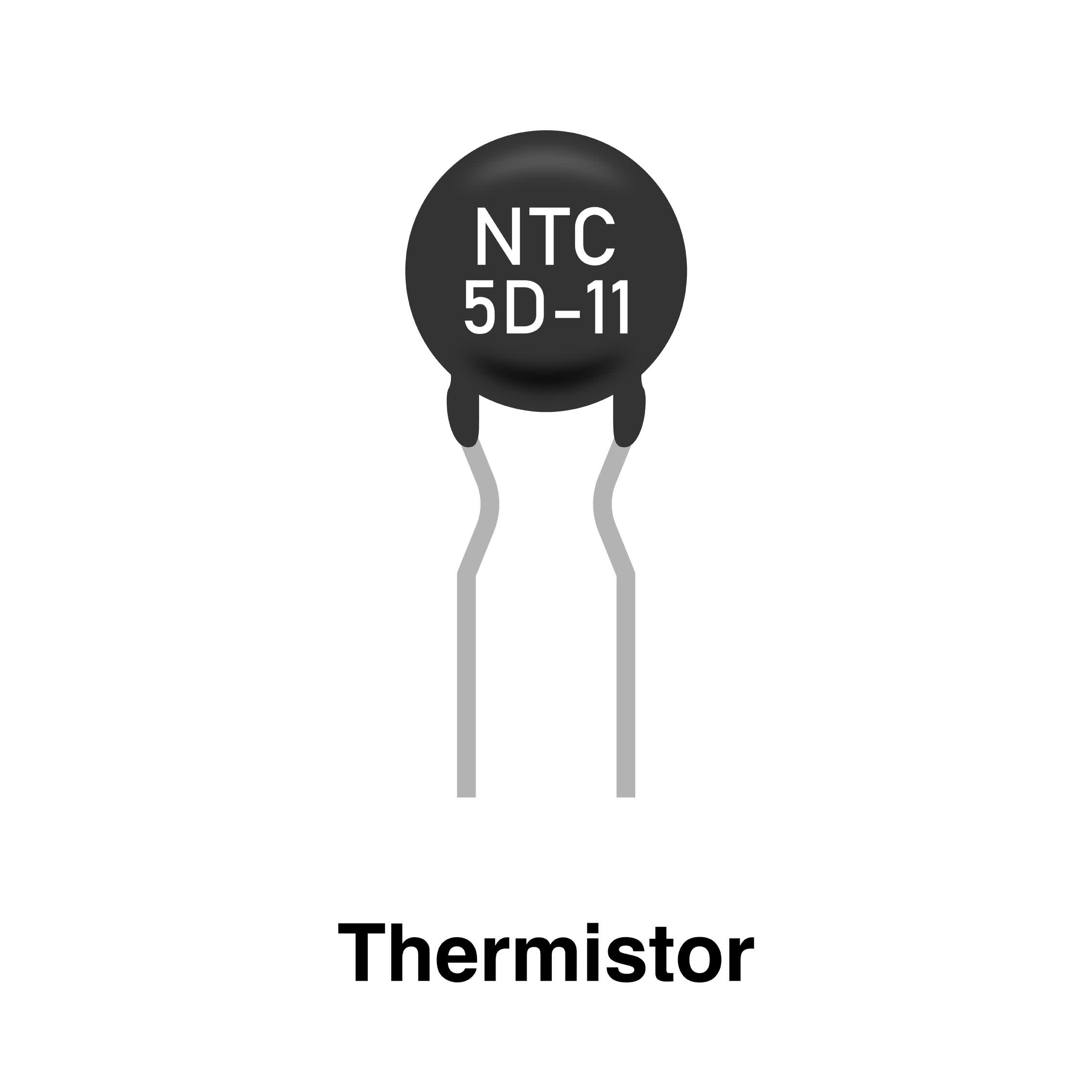
The circuit works by monitoring the voltage at the transistor's base. When the temperature rises, the thermistor resistance drops, increasing the base voltage. Once this reaches about 0.6V, the transistor switches on and activates the output device (buzzer or alarm).
The 0.6V threshold is a fundamental characteristic of silicon transistors. This voltage must be reached at the base for the transistor to switch from off to on state.
Light-sensing circuits
Light-dependent circuits use an LDR (Light Dependent Resistor) as the input sensor. An LDR's resistance decreases when light shines on it and increases in darkness.
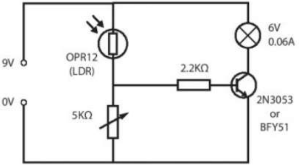
For automatic lighting that switches on when it gets dark, the LDR must be positioned as the top resistor in the potential divider. As darkness increases, the LDR resistance rises, increasing the voltage to the transistor base and switching on the light.
LDR Position Matters
The position of the LDR in the potential divider determines whether your circuit responds to light or darkness. Always check your circuit design matches your intended function.
Moisture-sensing circuits
Rain or moisture alarm circuits use a moisture sensor that creates a circuit path when water bridges its contacts. This allows current to flow to the transistor base, switching on an LED or buzzer to indicate the presence of water.
Resistor colour codes
Resistors use coloured bands to indicate their resistance value. Learning this code is essential for circuit construction.

The colour code follows this pattern:
- First two bands: Give the first two digits of the resistance value
- Third band: Shows the number of zeros that follow
- Fourth band: Indicates the tolerance (usually gold or silver)
Memory Aid for Colour Codes
"Bad Boys Race Our Young Girls But Violet Generally Wins" helps remember the sequence: Black(0), Brown(1), Red(2), Orange(3), Yellow(4), Green(5), Blue(6), Violet(7), Grey(8), White(9).
Reading a Resistor: Step-by-Step
For a resistor with Red, Violet, Orange, Gold bands:
- First band (Red): 2
- Second band (Violet): 7
- Third band (Orange): 3 zeros (000)
- Fourth band (Gold): ±5% tolerance
Result: 27,000Ω = 27kΩ ±5%
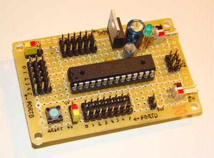
Building circuits
Before creating permanent circuits, it's wise to test your design using modelling boards. This allows you to check the circuit works correctly and make adjustments if needed.
Modelling boards
S-DeC boards feature rows of holes with metal contact strips underneath. Components are simply pushed into holes, making temporary connections easy to create and modify.
Soft boards use screws and cup washers on a wooden base. Wires are connected by wrapping them around screws, creating a secure but temporary connection method.
Loctronics systems use specially designed components that plug into baseboard sockets, making circuit construction quick and reliable for testing purposes.

Always Test Before Permanent Construction
Testing on modelling boards saves time and components. Many circuit problems can be identified and corrected at this stage, preventing costly mistakes in permanent circuits.
Permanent circuits
Once you've tested your circuit design, several methods exist for creating permanent versions:
Matrix boards are plastic boards with rows of holes. Components are inserted and soldered to terminal pins pushed through from the component side.
Strip boards feature parallel copper strips running across the board. Components are inserted from the top and soldered to the strips underneath. Breaks can be made in strips using a special tool to isolate different parts of the circuit.
Breadboards are useful for temporary connections during circuit development. They have rows of connected holes that allow components to be easily inserted and removed without soldering.
Printed circuit boards (PCBs)
PCBs represent the highest quality permanent circuit construction method. They consist of a thin layer of copper on a plastic substrate, with unwanted copper etched away to leave connection tracks.

Making a PCB
The PCB manufacturing process involves several careful steps:
PCB Manufacturing Process: Step-by-Step
- Design transfer: The circuit layout is drawn onto the copper surface using etch-resist materials
- Etching: The board is placed in ferric chloride solution, which dissolves unprotected copper
- Cleaning: The board is washed thoroughly and the etch-resist material removed
- Drilling: Small holes are drilled for component leads
- Assembly: Components are inserted and soldered to the copper tracks
Each step must be completed carefully to ensure a professional result.
Soldering techniques
Proper soldering is crucial for reliable circuit connections. Poor soldering is often the cause of circuit failures and can be difficult to identify.
Soldering equipment and technique
Use a 15-watt soldering iron with a 1.5mm tip for most PCB work. Always use flux-cored solder, which contains resin flux to ensure clean joints.
Essential Soldering Steps
- Heat both the copper track and component lead simultaneously
- Apply solder to the heated joint, not to the iron tip
- Allow solder to flow around the joint completely
- Remove the iron while keeping components still until the joint cools
- Trim excess wire leads with side cutters
Heat Protection: Heat-sensitive components like transistors and LEDs can be protected using crocodile clips as heat sinks attached to their leads.
Case design and housing
Once your circuit is complete, it needs proper housing for protection and user access. Case design must consider:
- Clear visibility of indicator lights
- Access to variable controls like potentiometer knobs
- Secure mounting of the circuit board
- Entry points for sensor leads
- Easy access for battery replacement
Cases can be made from various materials including acrylic, wood, or plastic enclosures. Both opaque and clear sections may be needed depending on the circuit's requirements.
Key Points to Remember:
- Potential dividers split voltage in proportion to resistance values - use this principle to control transistor switching
- Always design circuits using the input-process-output model to ensure systematic development
- Test circuits on modelling boards before creating permanent versions
- Learn the resistor colour code thoroughly - it's essential for circuit construction
- Practise proper soldering technique to avoid unreliable connections that cause circuit failures