Below-Ground Drainage (Leaving Cert Construction Studies): Revision Notes
Below-ground drainage
Below-ground drainage systems transport wastewater from where it enters the underground pipework to either a public sewer or a private septic tank. This critical infrastructure requires careful design, installation and maintenance to function effectively.
Understanding siphonage problems
Siphonage occurs when pressure differences create suction that can empty water traps, allowing sewer gases to enter buildings. Three main types affect drainage systems:
Self-siphonage
This happens when the waste pipe beneath an appliance runs completely full across its diameter into the stack. The flowing water reduces pressure inside the waste pipe, creating suction that pulls water from the appliance trap.
Self-siphonage Risk: When waste pipes run completely full, they create dangerous suction that can empty water traps and allow toxic sewer gases into the building.
Induced siphonage
When water flows down through the stack past a connecting waste pipe, the main flow creates suction within the waste pipe. This pulls water from the connected appliance trap.
Back pressure
This develops at the bottom of the stack, typically where it changes direction. Water flow slowing through the stack increases pressure, which builds up in the waste pipe and can force the appliance seal to fail.
Critical Failure Points: Back pressure typically occurs where stacks change direction at the bottom - these areas require careful design attention to prevent seal failure.
Function and design principles
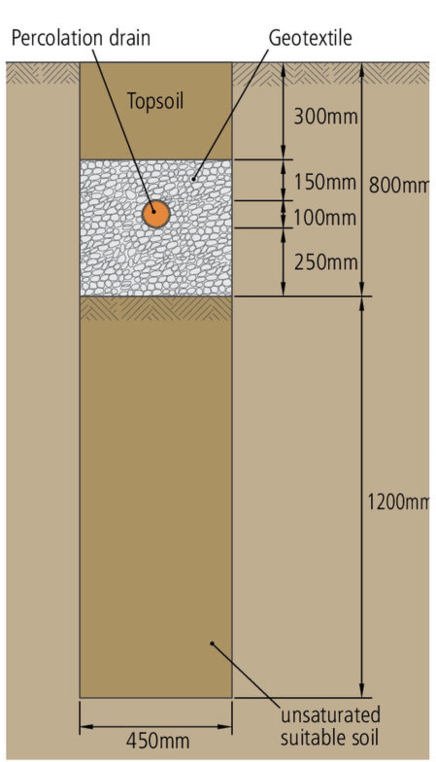
The primary role of below-ground drainage is moving wastewater from underground entry points to sewerage systems or septic tanks. In urban areas, homes typically connect to local authority sewers, whilst rural properties often use septic tanks with percolation areas.
Since underground pipework requires minimal maintenance once installed, the design must prioritise reliability:
Essential Design Principles:
- Keep the layout as simple as possible
- Minimise changes in direction or gradient
- Make connections in the direction of flow
- Allow branches to join at oblique angles
Materials and installation components
Modern installations commonly use uPVC (unplasticised polyvinyl chloride) piping due to its strength, flexibility, chemical resistance and ease of installation. However, concrete, cast iron and clay pipes are also suitable for underground drainage.
Installation Advantages: Pre-fabricated pipe sections and connectors simplify installation and ensure proper fitting connections. These components are readily available from builders' suppliers and speed up the installation process considerably.
Access points for maintenance
Underground drainage systems require various access points for inspection and maintenance:
Manholes
Used when drain depth exceeds 1 metre. These substantial structures need cast iron, pressed steel or precast concrete covers due to loading requirements. Internal dimensions range from 1200 x 750mm to 1200 x 840mm, built on minimum 150mm concrete bases.
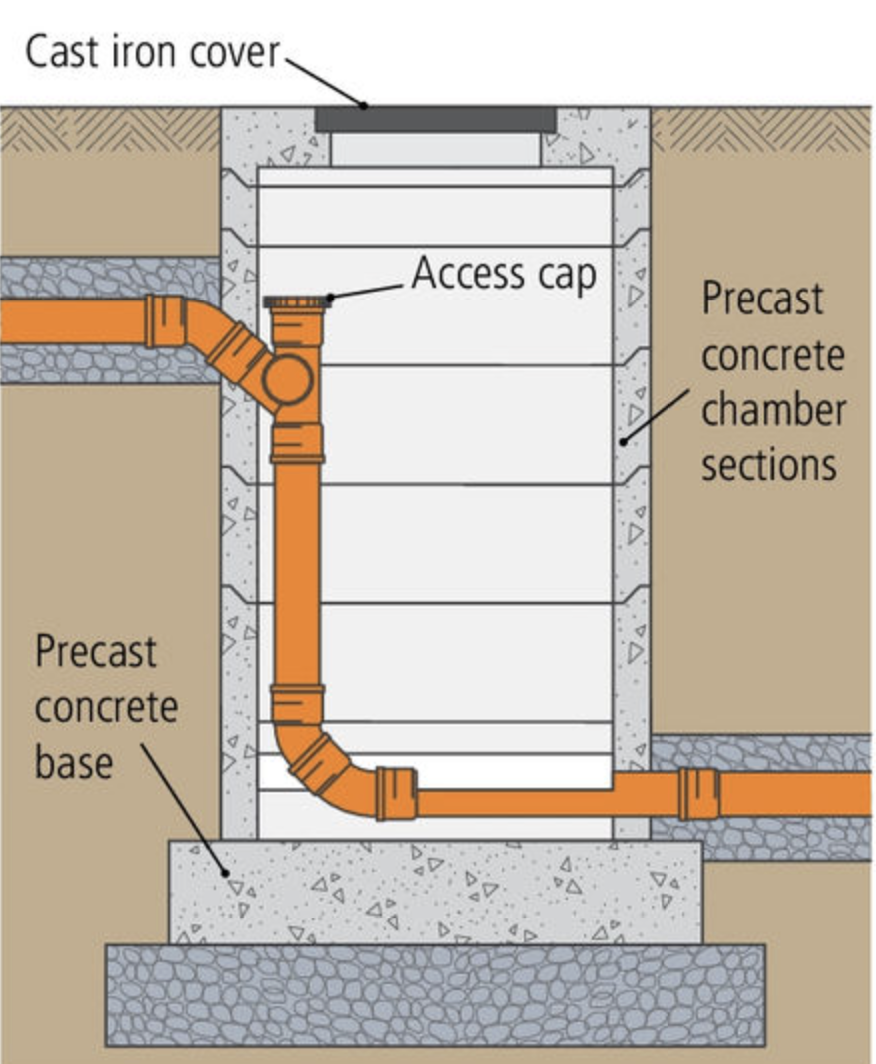
Inspection chambers
Installed for drain depths up to 1 metre. Modern construction often uses uPVC products rather than traditional concrete and brick. These provide access at key locations: drain heads, level changes, direction changes, and new connections to main drains.
Gully grates
Surface drainage points that connect to the underground system, typically handling rainwater and some waste discharge.
Access junctions and rodding points
Additional maintenance access points positioned strategically throughout the system to enable clearing potential blockages.
Backdrop manholes
Specialised manholes that handle significant level differences in the drainage system.
Ventilation requirements
Drainage systems connecting multiple properties need proper ventilation. Install vents at each house connection or wherever branch lengths exceed 6 metres. When pipework changes direction, use the largest possible radius to maintain smooth flow and reduce blockage risk.
Ensuring watertightness
Preventing leakage requires installing rubber seals at pre-formed pipe ends. Connect pipes squarely to avoid damaging these seals and maintain system integrity.
Connection Warning: Always connect pipes squarely to avoid damaging rubber seals - damaged seals lead to leakage and system failure.
Preventing blockages
Several design considerations help prevent blockage formation:
- Internal pipe surfaces must remain smooth
- Use adequate pipe diameter (typically 100mm minimum) for expected flow volumes
- Install pipes at correct gradients
- Use large radius bends for direction changes
- Prevent any objects projecting into the pipework
Installation specifications
Gradients and depths
Drainage pipes connecting to sewerage systems require proper gradients and installation depths. Standard pipe diameter is 100mm, with gradient requirements varying based on the number of connected dwellings and system span.
Trenching and backfill
Excavate trenches and backfill with aggregate to embed drainage pipes properly. The pipe bottom must sit 550mm below ground level, with 300mm topsoil over 500mm aggregate depth.
Depth Requirements: Proper burial depth is essential - insufficient depth can lead to pipe damage from surface loads, while excessive depth increases installation costs unnecessarily.
Inspection chambers
These provide drain access for regular inspection and maintenance. Position them at drain heads, level changes, direction changes, and where new connections join the main drain.
Chambers can use traditional concrete and brick construction or modern uPVC products that offer easier, cheaper and faster installation. The chamber sides slope or 'bench' to direct overflow back into the drainage channel.
For depths up to 1 metre, standard inspection chambers suffice. Beyond 1 metre depth, the structure becomes a manhole requiring stronger construction.
Testing the system
Underground drainage must be tested before backfilling to ensure system integrity. Three testing methods are available:
Air test
Air Test Procedure:
Step 1: Fit temporary vertical pipe sections (up-stands) to the system section being tested
Step 2: Seal one up-stand and attach a compressor or pump to the other
Step 3: Pump air into the system and maintain pressure for three minutes
Result: Any immediate pressure drop indicates an air leak, giving instant results
Water test
Water Test Procedure:
Step 1: Install temporary up-stands and fill the system section with water
Step 2: Maintain the water level for 24 hours for acceptable results
Requirements: Water height should be 1.5 metres, with a maximum of 4 metres
Scope: This test can assess entire underground systems including access points
Smoke test
Smoke Test Procedure:
Step 1: Pump smoke through the drain section length
Step 2: Seal the up-stand once full of smoke
Step 3: Maintain pressure for five minutes whilst observing for escaping smoke
Effectiveness: This method effectively identifies leak sources but isn't recommended for uPVC pipework
Testing Requirement: All underground drainage systems MUST be tested before backfilling - failures discovered after backfilling require expensive excavation and repair work.
Key Points to Remember:
- Siphonage problems (self-siphonage, induced siphonage, back pressure) can empty traps and allow sewer gases into buildings
- Below-ground drainage transfers wastewater from underground entry points to sewers or septic systems
- Use inspection chambers for depths up to 1m, manholes for greater depths
- Test all underground drainage systems before backfilling using air, water, or smoke tests
- Proper gradients, adequate pipe diameters (typically 100mm) and watertight connections are essential for system success