The Geometry of Mining (Leaving Cert DCG): Revision Notes
The Geometry of Mining
Understanding mining geometry
Mining geometry involves the mathematical and graphical analysis of terrain and underground features to support mining operations. This field combines surveying principles with geometric techniques to help mining engineers plan efficient and safe extraction of materials from both surface and underground locations.
The geometry of mining is essential for determining optimal mining routes, calculating volumes of material to be removed, and ensuring structural stability during operations. It also helps in assessing visibility between different points on the terrain, which is crucial for safety and operational planning.
Mining geometry serves as the foundation for virtually all mining operations, from initial site assessment through to final rehabilitation. The techniques you'll learn form the basis for more advanced mining engineering concepts.
Working with contour maps
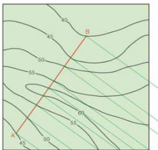
Contour maps form the foundation of mining geometry analysis. These maps use curved lines to represent points of equal elevation across a landscape. Each contour line connects all points that share the same height above sea level.
Key features of contour maps:
- Contour lines never cross each other
- Closer lines indicate steeper slopes
- Lines are typically drawn at regular elevation intervals (such as every 5 metres)
- The spacing between elevation values is called the contour interval
Understanding how to read these elevation patterns is essential for mining planning, as they reveal the three-dimensional shape of the terrain that must be navigated or modified during mining operations.
Common Mistake: Remember that contour lines can never cross each other because a single point cannot have two different elevations simultaneously. If your lines appear to cross, check your interpretation of the contour map.
Creating profiles from contour maps
A profile is a cross-sectional view that shows the elevation changes along a specific line across the terrain. This technique transforms the bird's-eye view of a contour map into a side view that clearly shows the ups and downs of the landscape.
Step-by-step profile construction method
Worked Example: Creating a Terrain Profile
Step 1: Establish the profile line Draw a straight line between your two points of interest on the contour map. This line represents the path along which you want to analyse the terrain.
Step 2: Identify intersection points Mark where your profile line crosses each contour line. These intersection points will become key elevation points on your profile drawing.
Step 3: Set up the profile grid Create a horizontal baseline for your profile drawing. The spacing between elevation lines on your profile should match the scaled equivalent of your contour interval.
Step 4: Project elevation points Draw perpendicular lines from each contour intersection point down to your profile baseline. This transfers the elevation information from the map to your cross-section.
Step 5: Plot the profile shape Connect the projected points to create a continuous line showing the terrain's shape along your chosen route.
Line of sight analysis
Line of sight calculations help determine whether one point on the terrain can be seen from another. This is particularly important in mining operations for planning observation points, communication systems, and safety protocols.
Visibility determination process
To check if an object at one location can be seen from another point:
Worked Example: Determining Visibility
Sight line construction: Draw a straight line from the viewing point towards the target location on your profile drawing. This represents the path light would travel between the two points.
Obstacle identification: Check whether any part of the terrain profile rises above this sight line. If the terrain blocks the sight line at any point, the target object will not be visible.
Height calculations: When placing objects (such as equipment or structures) at the target location, you can determine the minimum height needed for visibility by extending the sight line to meet a vertical line at the target position.
Line of sight analysis is crucial for mining safety. It helps determine optimal placement of warning systems, communication equipment, and supervision points throughout the mining site.
Practical applications in mining
Mining geometry principles support numerous practical applications in the industry:
Surface mining planning:
- Determining optimal pit layouts
- Calculating overburden removal requirements
- Planning access roads and ramps
Underground operations:
- Designing tunnel routes that follow favourable geological conditions
- Planning ventilation systems
- Ensuring structural stability in excavated areas
Safety considerations:
- Establishing sight lines between work areas
- Planning escape routes
- Positioning safety equipment and communication systems
Safety First: All geometric planning in mining must prioritise worker safety and regulatory compliance. Beautiful mathematical solutions are worthless if they create hazardous working conditions.
Exam tips for mining geometry problems
Study Strategy for Success:
Always start with the basics:
- Clearly identify what information is given
- Understand what you need to find
- Choose the appropriate geometric technique
Work systematically:
- Follow the step-by-step approach for profile construction
- Double-check your measurements and projections
- Label all important points and lines clearly
Check your work:
- Ensure your profile makes logical sense given the contour map
- Verify that sight lines follow straight paths
- Confirm that elevation values are consistent throughout your solution
Key Points to Remember:
- Contour maps show elevation using curved lines that connect points of equal height
- Profiles are cross-sectional views created by projecting contour intersections onto a baseline
- Line of sight analysis uses straight lines on profiles to determine visibility between points
- Systematic approach is essential - follow each step carefully to avoid errors
- Mining geometry combines surveying principles with geometric techniques to support safe and efficient mining operations