Method Two: Radial Elements Method (Leaving Cert DCG): Revision Notes
Method Two: Radial Elements Method
What is the radial elements method?
The radial elements method is a specialised technique used to find the intersection between solids, particularly when cones or pyramids are being penetrated by other solids. This method becomes essential when the standard limits method cannot be applied effectively to these curved or pointed geometric forms.
Think of radial elements as imaginary lines that radiate outward from a central point (like spokes on a bicycle wheel). In geometric terms, these elements extend from the apex (tip) of a cone or pyramid through the intersecting solid.
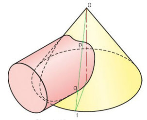
The key principle: radial elements work like invisible threads stretching from the pointed tip of your geometric shape through the intersecting object, helping you map exactly where the two surfaces meet.
When should you use this method?
The radial elements method is your go-to solution for specific geometric scenarios where traditional approaches fall short.
Use the radial elements method when:
- A cone or pyramid is intersected by another solid
- The limits method proves inadequate for the geometric forms involved
- You need to find precise intersection points on curved or angled surfaces
- Working with complex three-dimensional intersections
The key advantage is that this method works effectively with the natural geometry of cones and pyramids, using their apex as a reference point.
Understanding radial elements
A radial element is a straight line drawn from the apex of a cone or pyramid that passes through both intersecting solids. This element helps locate specific points where the surfaces of the two solids meet, creating the line of intersection.
In practical terms, when you draw a radial element from the apex through the second solid, you can identify exactly where this line intersects both geometric forms. These intersection points can then be projected onto different orthographic views to build up the complete intersection curve.
Step-by-step process
The radial elements method follows a systematic approach that builds precision through careful projection work.
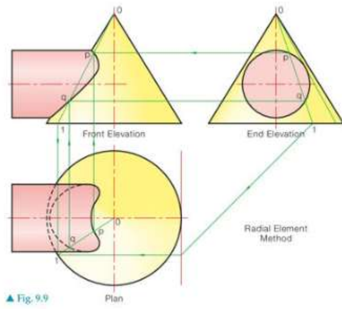
Step 1: Set up your orthographic views
Begin with the standard three orthographic projections:
- Front elevation
- End elevation
- Plan view
Step 2: Identify the apex
Locate the apex (tip) of your cone or pyramid in all views. This serves as the starting point for all radial elements.
Step 3: Draw radial elements
From the apex, draw straight lines (radial elements) that pass through the intersecting solid. Each element should extend far enough to clearly show where it enters and exits both geometric forms.
Step 4: Find intersection points
Mark the points where each radial element crosses the surfaces of both solids. These points lie on the line of intersection between the two shapes.
Step 5: Project between views
Transfer these intersection points between your orthographic views using standard projection techniques. This builds up the intersection curve in each view.
Step 6: Join the points
Connect the intersection points with a smooth curve to show the complete line of intersection.
Practical applications
The method works particularly well for complex geometric intersections where precision is essential.
Worked Example: Cone and Prism Intersection
Consider a cone being penetrated by a rectangular prism:
Step 1: Draw radial elements from the cone's apex through key points of the prism Step 2: Mark where each element crosses both the cone surface and prism faces Step 3: Project these intersection points to all three orthographic views Step 4: Connect the points to reveal the intersection curve
Result: A smooth curve showing exactly how the prism cuts through the conical surface
Common applications include:
- Cone and prism intersections: Where a cylindrical or prismatic shape passes through a conical form
- Pyramid penetrations: Such as a hexagonal-based pyramid with a square hole cut through it
- Complex curved intersections: Where traditional methods struggle with the geometry
Key terminology
Understanding these fundamental terms is essential for mastering the radial elements method.
Essential Definitions:
- Apex: The pointed tip of a cone or pyramid from which radial elements originate
- Radial element: A straight line extending from the apex through the intersecting solid
- Line of intersection: The curve or line where two solid surfaces meet
- Bend points: Specific points where the intersection line changes direction or character
- Orthographic projection: The standard technical drawing views (plan, front elevation, end elevation)
Exam tips
Success in examinations requires both understanding the method and demonstrating clear working.
Critical Exam Strategies:
- Always start by clearly identifying the apex in all views
- Draw radial elements as construction lines (use light, dashed lines initially)
- Take time to accurately project intersection points between views
- Remember that intersection lines should be smooth curves unless there's a genuine geometric reason for sharp changes
- Label your construction clearly to demonstrate your method to the examiner
Common mistakes to avoid
Avoid These Critical Errors:
- Forgetting to extend radial elements far enough through both solids
- Inaccurate projection between orthographic views
- Drawing intersection curves that don't follow the natural geometry of the solids
- Missing intersection points where radial elements cross solid boundaries
- Starting radial elements from incorrect points instead of the true apex
Key Points to Remember:
- Radial elements always start from the apex of cones or pyramids
- This method works when limits method fails for curved and pointed solids
- Accurate projection between views is essential for correct results
- Intersection points lie where radial elements cross both solid surfaces
- The final intersection is a smooth curve connecting all the located points