Overview of Milling (Leaving Cert Engineering): Revision Notes
Overview of Milling
What is milling?
Milling is a machining process that shapes metal and plastic engineering components. This process is commonly used in tool making and automotive industries. The milling operation employs a multi-edged cutting tool that rotates in a fixed position, which can be vertical, horizontal, or at an angle.
The workpiece is secured to a machine table where it can be fed into the rotating cutting tool. Movement occurs along the X, Y, and Z axes, providing precise control over the machining operation.
The precision control provided by X, Y, and Z axis movement is what makes milling particularly suitable for creating complex geometrical shapes and maintaining tight dimensional tolerances in engineering components.
Machine movements and control
Milling machines operate with three main types of movement that allow for precise machining operations:
- Cross travel - horizontal movement across the workpiece
- Long travel - longitudinal movement along the workpiece
- Vertical travel - controls the depth of cut
These movements enable operators to create complex shapes and precise dimensions on engineering components. The combination of these three axes of movement provides the flexibility needed for sophisticated machining operations.
Modern CNC milling machines can coordinate all three axes simultaneously, allowing for the creation of complex 3D shapes and contoured surfaces that would be impossible with manual operation.
Types of milling machines
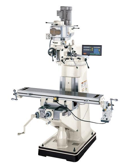
Vertical milling machines
In vertical milling machines, the cutting tool is mounted in a vertically positioned chuck. The workpiece remains fixed to the machine table, typically secured with a machine vice. The table can move along all three axes, allowing for easy workpiece positioning.
Turret milling machines are a variation of vertical mills. They function similarly but feature the ability to rotate and pivot the machine head to different angles. This capability is particularly useful for machining angled surfaces. The primary milling operation performed on vertical machines is face milling.
Face milling on vertical machines provides excellent surface finishes and is ideal for creating flat surfaces, shallow slots, and pockets in workpieces.
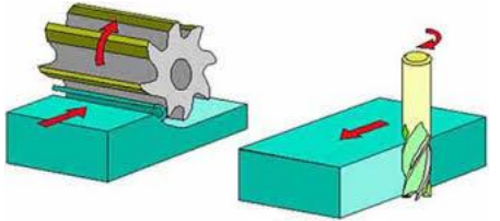
Horizontal milling machines
Horizontal milling machines are similar in size to vertical mills. The machine table operates using the same principles and can move along all three axes. However, the key difference is that the cutting tool is hollow and mounted on a horizontally mounted arbour (a round steel bar).
The main type of milling operation carried out on horizontal machines is known as peripheral milling or slab milling.
Horizontal milling machines excel at removing large amounts of material quickly, making them particularly effective for roughing operations and machining long, straight surfaces.
Types of milling cutters
Different cutting tools are designed for specific milling operations. Chuck-mounted cutters are commonly used on vertical milling machines:
End mills
- Used for general milling operations on top and side surfaces
- Feature 4, 6, 8 or more cutting edges
- Can create slots, but only open-ended slots
Slot drills
- Designed for milling internal slots
- Have only two cutting edges
- Less efficient than end mills due to fewer cutting edges
The reduced number of cutting edges on slot drills means they cut more slowly than end mills, but their design allows them to plunge directly into material to create closed slots.
Angle cutters
- Specifically used for creating chamfers along edges
- Provide precise angular cuts
Ball-nosed slot drill
- Used for cutting channels into material
- Functions similarly to standard slot drills
- Creates rounded channel bottoms
Corner-rounding cutter
- Used to mill fillets along edges
- Creates smooth, rounded transitions
Dovetail cutter
- Specialised for machining dovetail joints
- These machined dovetails are also found on laith topsides
Selecting the correct cutter type is essential for achieving the desired surface finish and dimensional accuracy. Each cutter design is optimised for specific cutting conditions and material removal requirements.
Feed rates and machining cycles
Feed rate refers to the speed at which the cutting tool moves along or across the workpiece. This parameter is controlled by the operator and significantly affects both finish quality and production time.
Understanding feed rates
- Slower feed rates produce superior surface finishes but increase production time
- Higher feed rates reduce machining time but may compromise surface quality
Finding the optimal feed rate requires balancing production efficiency with quality requirements. Too fast can cause poor finishes or tool damage, while too slow wastes time and may cause work hardening in some materials.
Machining cycles
Two main types of cycles are used in milling operations:
- Roughing cycle - uses high feed rates for the majority of machining, prioritising time efficiency
- Finishing cycle - employs lower feed rates and is only used for the final passes to achieve the desired surface finish
Most professional milling operations use a combination of both cycles - roughing to remove bulk material quickly, followed by finishing passes to achieve the required surface quality and dimensional accuracy.
Key Points to Remember:
- Milling uses rotating multi-edged cutting tools to shape metal and plastic components
- Vertical machines have vertically mounted tools and primarily perform face milling
- Horizontal machines use horizontally mounted arbours and excel at peripheral/slab milling
- Different cutters serve specific purposes - end mills for general work, slot drills for internal slots, specialty cutters for specific features
- Feed rate directly affects surface finish quality - slower feeds give better finishes but take longer