Taper Turning (Leaving Cert Engineering): Revision Notes
Taper Turning
What is taper turning?
Taper turning is a machining process used to create angled or tapered surfaces on cylindrical workpieces using a laith. Instead of cutting parallel to the workpiece axis, the cutting tool moves at an angle to produce a gradually changing diameter along the length of the component.
Unlike standard turning operations that maintain constant diameter, taper turning creates a controlled variation in diameter to produce conical or angled surfaces on components.
There are three main methods available for producing tapers on a laith, each suited to different types of work and taper requirements.
Methods of taper turning
Method 1: Turning the compound slide
This method is specifically designed for creating points or short tapers on workpieces. The process involves adjusting the compound slide mechanism on the laith.
Setup procedure:
- The compound slide securing bolts must be loosened first to allow the slide to rotate freely
- The slide is then rotated to the required angle, which can be read from the degree markings on the machine
- Important calculation: When creating a point, the compound slide must be set to half the required point angle
Worked Example: Setting Compound Slide for Point Angle
If a point angle is required:
- Compound slide setting = Point angle ÷ 2
- Compound slide setting =
Therefore, the top slide must be set to
This method provides excellent control for precision work but is limited to shorter lengths due to the travel restrictions of the compound slide.
Method 2: Offsetting the tailstock
This technique is used for machining longer tapers that cannot be produced by rotating the compound slide alone. The method involves deliberately moving the tailstock away from its normal centre position.
How it works:
- The tailstock, which normally runs on the same axis as the machine spindle, is adjusted so it runs off centre
- The amount of displacement (offset distance) combined with the length of the component being machined determines the final angle of taper
- The cutting tool operates normally - it's the workpiece geometry that creates the taper
- The work is secured between two centres for stability during machining
Knowledge of trigonometry is essential to calculate the correct offset distance accurately. This ensures the finished component meets the required taper specifications. Incorrect calculations will result in improper taper angles.
Method 3: Taper turning attachment bar
This represents an alternative approach for producing longer tapers and offers several advantages over the offset method.
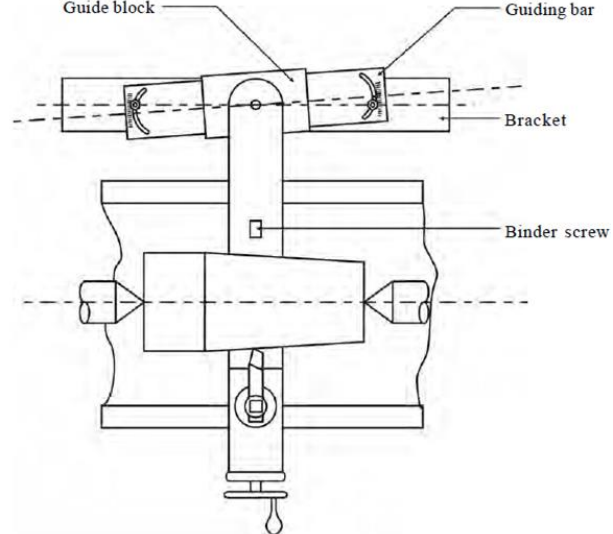
System components:
- Guide bar: Attached behind the laith bed
- Guide block: Connects to the cross slide leadscrew
- Bracket: Provides mounting points
- Binder screw: Secures the setup
The taper turning attachment is a specialised accessory that provides more consistent results than the tailstock offset method for longer tapers, especially when multiple identical components are required.
Operation principle:
- The guide bar is set to the required taper angle
- As the saddle moves along the component length, the attachment bar creates simultaneous movement of the cutting tool on two axes
- This dual-axis movement is essential for cutting the taper correctly
- The system effectively moves the cutting tool in and out across the component as it travels longitudinally
This method provides consistent results for longer tapers and can be more accurate than the offset method for certain applications.
Key Points to Remember:
- Three methods exist: compound slide (short tapers), tailstock offset (long tapers), and taper attachment bar (long tapers)
- Compound slide angle rule: Set the slide to half the required point angle ( point = slide setting)
- Tailstock offset requires trigonometry to calculate the correct displacement distance
- Taper attachment creates dual-axis movement for accurate longer tapers
- Choose the method based on taper length - short tapers use compound slide, longer tapers use offset or attachment methods