Generators, Alternating Current, and Mutual Inductance (Leaving Cert Physics): Revision Notes
Generators, Alternating Current, and Mutual Inductance
Electric generators
An electric generator is a device that transforms kinetic (mechanical) energy into electrical energy through the principle of electromagnetic induction. When a conductor moves through a magnetic field, or when the magnetic field around a conductor changes, an electromotive force (EMF) is induced in the conductor.
The principle of electromagnetic induction discovered by Michael Faraday in 1831 forms the foundation of all electric generators. This fundamental law states that a changing magnetic field through a conductor will always induce an EMF, regardless of how that change occurs.
The simple AC generator
The AC generator, also called an alternator, produces alternating current that constantly changes direction. Understanding how it works helps explain the fundamental principles of electromagnetic induction.
The basic components of an AC generator include:
- Permanent magnets creating a uniform magnetic field
- Rotating coil (armature) that spins within the magnetic field
- Slip rings that maintain electrical contact while allowing continuous rotation
- Carbon brushes that provide external circuit connections
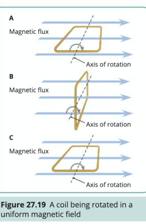
As the coil rotates within the magnetic field, the amount of magnetic flux passing through it changes continuously. When the coil is perpendicular to the magnetic field lines, maximum flux passes through it. When parallel to the field lines, minimum flux passes through.
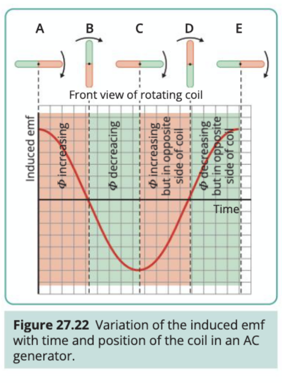
The changing magnetic flux induces an EMF in the coil according to Faraday's law. As the coil completes one full rotation, the induced EMF varies in a smooth, sinusoidal pattern. This creates the characteristic alternating current waveform that oscillates between positive and negative values.
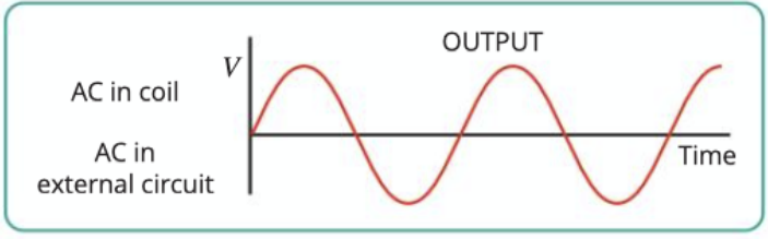
The slip rings are essential for AC generation because they allow the coil to rotate continuously whilst maintaining electrical contact with the external circuit. This means the alternating current produced in the coil is transmitted directly to the external circuit without modification.
The simple DC generator
The DC generator produces current that flows in only one direction, though the magnitude may vary. The key difference from an AC generator lies in how the electrical connection is made to the external circuit.
Instead of slip rings, the DC generator uses a split-ring commutator. This consists of two semicircular metal segments separated by insulation. As the coil rotates, the commutator segments alternately connect with each carbon brush.
The split-ring commutator acts like an automatic switching device. Every half rotation, it reverses which end of the coil connects to which terminal in the external circuit. This ensures that current always flows in the same direction through the external circuit, even though the current in the rotating coil itself alternates direction.
The result is pulsating direct current - current that varies in magnitude but maintains the same direction. While not perfectly steady, this represents a significant improvement over pure alternating current for applications requiring unidirectional current flow.
Key differences between generators
| Feature | AC Generator | DC Generator |
|---|---|---|
| Output current | Alternating direction | Single direction |
| Electrical contact | Slip rings | Split-ring commutator |
| Current waveform | Smooth sinusoidal | Pulsating DC |
| Complexity | Simpler construction | More complex commutator |
| Applications | Mains electricity supply | Battery charging, DC motors |
Alternating current
What is alternating current?
Alternating current (AC) is electric current that periodically changes direction. Unlike direct current, which flows steadily in one direction, AC current oscillates back and forth through the circuit at regular intervals.
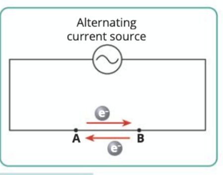
In an AC circuit, electrons don't flow continuously from one end to the other. Instead, they oscillate back and forth, changing direction many times per second. The frequency of this oscillation determines the AC frequency, measured in hertz (Hz).
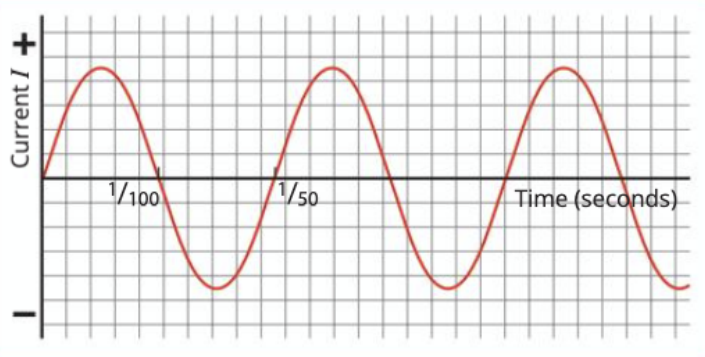
In Ireland and the UK, mains electricity supply operates at 50 Hz, meaning the current changes direction 100 times every second (50 complete cycles). Each complete cycle takes 1/50th of a second to complete.
AC voltage and current characteristics
AC voltage and current follow a sinusoidal pattern when plotted against time. This smooth, wave-like pattern results from the rotating coil generator design, where the EMF varies as the sine of the rotation angle.
The sinusoidal waveform has several important characteristics:
- Peak value: The maximum voltage or current reached in either direction
- Period: The time taken for one complete cycle
- Frequency: The number of complete cycles per second
- Amplitude: The maximum displacement from zero
Heating effects of alternating current
Even though AC constantly changes direction, it still produces heat when flowing through a resistor. This occurs because the heating effect depends on the square of the current (), and squaring eliminates any negative values.
The heat produced by alternating current follows the same pattern as the current itself, varying sinusoidally with time. However, the practical heating effect we observe represents an average over time.
RMS values of AC
Since AC constantly varies, we need a way to compare it with steady DC. The root mean square (RMS) value provides this comparison by giving the equivalent DC value that would produce the same heating effect.
For sinusoidal AC:
- where is the peak current
- where is the peak voltage
The RMS value is approximately 0.707 times the peak value.
When we say mains electricity is 230V, this refers to the RMS voltage - the peak voltage is actually about 325V.
Worked Example: Calculating RMS Values
Given: Peak voltage
Step 1: Apply the RMS formula
Step 2: Substitute the values
This confirms why mains electricity is rated at 230V RMS.
For power calculations with AC:
Using an oscilloscope to show AC
An oscilloscope displays electrical signals as waveforms on a screen, making it invaluable for studying AC characteristics. When connected to an AC source, the oscilloscope shows the familiar sinusoidal pattern.
The oscilloscope can measure:
- Peak voltage and peak-to-peak voltage
- Frequency and period of the AC signal
- Phase relationships between different AC signals
- Waveform shape to identify distortions or harmonics
By adjusting the time base and voltage scales, you can examine AC signals in detail and verify theoretical predictions about amplitude, frequency, and waveform shape.
Mutual inductance
Understanding mutual inductance
Mutual inductance occurs when a changing electric current in one coil produces a changing magnetic field that induces an EMF in a nearby coil. This represents electromagnetic coupling between two separate circuits.
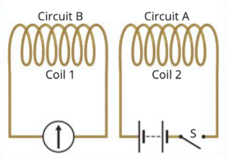
The phenomenon depends on several key principles:
- A changing current in the first coil (primary) creates a changing magnetic field
- This changing magnetic field extends into the surrounding space
- If a second coil (secondary) is placed within this changing field, an EMF is induced in it
- The magnitude of the induced EMF depends on how rapidly the current changes
Factors affecting mutual inductance
The strength of mutual inductance between two coils depends on several factors:
Distance between coils: Closer coils experience stronger magnetic coupling. As distance increases, the magnetic field from the primary coil becomes weaker at the secondary coil location.
Coil orientation: Coils aligned with their axes parallel show maximum mutual inductance. When perpendicular, mutual inductance approaches zero.
Number of turns: More turns in either coil increase the mutual inductance. The primary coil with more turns produces a stronger magnetic field, while the secondary coil with more turns captures more flux.
Core material: Placing the coils on the same soft iron core dramatically increases mutual inductance by concentrating and directing the magnetic field lines through both coils.
The most significant factor affecting mutual inductance is the core material. Using a soft iron core can increase mutual inductance by factors of hundreds or thousands compared to air core arrangements.
Practical applications
Mutual inductance forms the basis for many important electrical devices:
Transformers: Use mutual inductance to change AC voltage levels. The changing current in the primary coil induces a proportional EMF in the secondary coil, with the voltage ratio depending on the turns ratio.
Wireless charging: Modern wireless charging systems use mutual inductance between a charging pad (primary coil) and the device being charged (secondary coil).
Induction motors: The rotating magnetic field in the stator windings induces currents in the rotor through mutual inductance, creating the torque needed for rotation.
Radio antennas: Transmitting antennas use mutual inductance to couple electromagnetic energy to receiving antennas at distant locations.
Key Points to Remember:
-
AC generators use slip rings to produce alternating current, while DC generators use split-ring commutators to produce direct current
-
RMS values allow us to compare AC with DC - the RMS value equals the DC value that would produce the same heating effect
-
Mutual inductance occurs when changing current in one coil induces EMF in another nearby coil - this principle underlies transformers and many other electrical devices
-
Frequency of AC in Ireland and the UK is 50 Hz, meaning 50 complete cycles per second
-
The heating effect of AC depends on the RMS value, not the peak value, because power calculations use