Frames of Reference and Relativity (HSC SSCE Physics): Revision Notes
Frames of Reference and Relativity
What are frames of reference?
A frame of reference is the viewpoint from which an observer measures and describes motion. Different observers in different frames may see the same event very differently.
Galileo's Thought Experiment
Galileo described a famous thought experiment: imagine a sailor on a ship moving at steady speed who drops an object from the mast. From the sailor's viewpoint, the object falls straight down. However, an observer standing on shore would see the object follow a curved (parabolic) path. Both observers are correct - they're simply viewing the motion from different frames of reference.
Inertial frames of reference
Newton agreed with Galileo's reasoning and introduced the concept of inertial frames of reference. These are frames that are either:
- Stationary, or
- Moving at constant velocity (not accelerating or changing direction)
An inertial frame is one where Newton's first law of motion applies with very good accuracy. Any small departures from this law can be considered negligible.
Examples of inertial frames:
- A spaceship moving at constant velocity through space
- A table sitting on the ground
- An aeroplane cruising at steady speed and altitude
Non-inertial frames of reference
Non-inertial frames are those that are accelerating or changing direction. When you're in a non-inertial frame, you can detect that you're accelerating - you feel forces that wouldn't exist in an inertial frame.
Examples of non-inertial frames:
- A merry-go-round (rotating, constantly changing direction)
- An aeroplane taking off or landing (accelerating)
- A car going around a corner (changing direction)
Galilean transformations
Classical physics assumes that all inertial coordinate systems are equivalent. We can mathematically relate measurements made in different inertial frames using Galilean transformations.
Consider two frames of reference in two dimensions:
- Frame uses coordinates and is considered stationary
- Frame uses coordinates and moves relative to with velocity
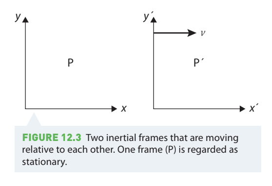
Suppose the two coordinate systems initially coincide at time , but then moves away from . The distance between them after time interval is .
The transformation equations
If frame is moving parallel to the -axis with speed :
Similarly, if moving parallel to the -axis:
These equations allow us to convert position measurements from one frame to another.
Time is invariant in classical physics
The Classical Assumption About Time
An important assumption in classical (Newtonian) physics is that time is invariant - it passes at the same rate in all frames of reference. A clock in frame and a clock in frame tick at exactly the same rate, so is the same in both frames.
This assumption will later be challenged by Einstein's theory of special relativity!
Important notes
The transformation equations depend on which frame you choose as "stationary". If you chose as stationary instead, then would be moving with velocity relative to , and you'd need to adjust the signs in the equations accordingly.
If the velocity has components in both and directions, you must use the appropriate component ( or ) in each transformation equation.
Worked Example: Position in Different Frames
Problem: A car travels at through an intersection. After , what is the position of the car with respect to coordinates based on: a) the intersection? b) the car?
The car represents the primed coordinate frame.
Solution:
| Step | Working | Explanation |
|---|---|---|
| Given | , | Identify the relevant data |
| Part a | Use the Galilean transformation equation | |
| At , the car was at the intersection so | ||
| The car is 120 m from the intersection | ||
| Part b | Rearrange to make the subject | |
| Substitute values | ||
| This makes sense - the car hasn't moved relative to itself! |
Principles of classical relativity
Galileo and Newton established fundamental principles about motion in different frames of reference:
1. The laws of motion are the same in all inertial frames of reference
Newton's laws work equally well whether you're on a smoothly moving train or standing on the platform. You can perform physics experiments and get the same results in any inertial frame.
2. Conservation laws apply in all inertial frames
While observers in different frames will measure different values for velocities, energies and momenta, they will all agree that energy is conserved and momentum is conserved.
3. All inertial frames are equivalent - no frame is more "correct" than another
There is no privileged or "absolute" inertial frame. If you're on a train travelling steadily at west across a flat plain, it's equally valid to say:
- "I'm moving at west relative to Earth", or
- "I'm stationary and Earth is moving at east relative to me"
As long as your motion is smooth and at constant velocity, there's no experiment you can perform to determine whether you're "really" moving or "really" stationary. Both descriptions are equally valid.
Relative velocities
We can calculate velocities in different frames using vector addition. The key principle is:
The Principle of Relative Velocities
The velocity of A relative to B equals the velocity of A relative to C plus the velocity of C relative to B:
This might seem complicated, but it matches our intuition. Let's see how this works with a practical example.
Example: Aeroplane flying with wind
Consider an aeroplane flying from Sydney to Perth. At cruising altitude (around ), there's usually a strong westerly wind (blowing from west to east). The plane's direction is almost exactly parallel to the wind direction.
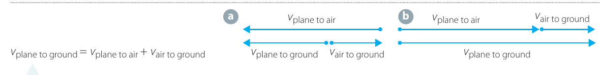
The plane's velocity relative to the ground is:
When flying westbound (Sydney to Perth), the wind opposes the plane's motion, so the ground speed is lower than the airspeed. This makes the westbound flight take longer (about 4 hours 25 minutes).
When flying eastbound (Perth to Sydney), the wind assists the plane, increasing the ground speed. This shortens the flight time (about 3 hours 50 minutes).
Worked Example: Aeroplane Velocity with Crosswind
Problem: An aeroplane is aiming due north at a speed of through the air. There is a westerly wind (coming from the west) of .
a) Draw a vector diagram showing the velocity of the plane relative to the ground. b) What is the speed of the plane relative to the ground? c) What is the complete velocity of the plane relative to the ground (magnitude and direction)?
Solution:
Part a) Vector diagram:
The plane's velocity relative to the ground equals its velocity relative to the air plus the air's velocity relative to the ground. Since the plane aims north and the wind blows from west to east, these vectors are perpendicular.
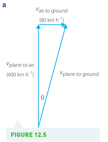
Part b) Speed calculation:
Using Pythagoras' theorem:
Part c) Direction calculation:
To find the angle east of north:
Final answer: The velocity of the plane relative to the ground is 408 km·h⁻¹ at bearing N11°E.
Investigation: Relative motion and frames of reference
Aim
To observe motion in different frames of reference - both inertial (constant velocity) and non-inertial (accelerating).
Materials
- Several sheets of white paper
- Carbon paper
- Large metal ball bearing
- Ramp
- Potter's wheel, lazy susan or record turntable
- 2 dissecting boards or similar-sized flat surfaces
- Graph paper
- Scissors
- Adhesive tape
- Video recording camera or smartphone
- Frame to support the camera (a ripple tank frame works well)
Safety considerations
Safety First
| Hazard | Risk Management |
|---|---|
| Large metal ball bearings can cause injuries | Keep the ball bearing safely on the table and use only in the experiment |
Consider and document any other risks specific to your setup, such as:
- Rotating equipment (turntable) - keep fingers clear
- Camera support stability - ensure it cannot fall
- Work area - keep clear of obstacles
Method
Part A: Inertial frame of reference
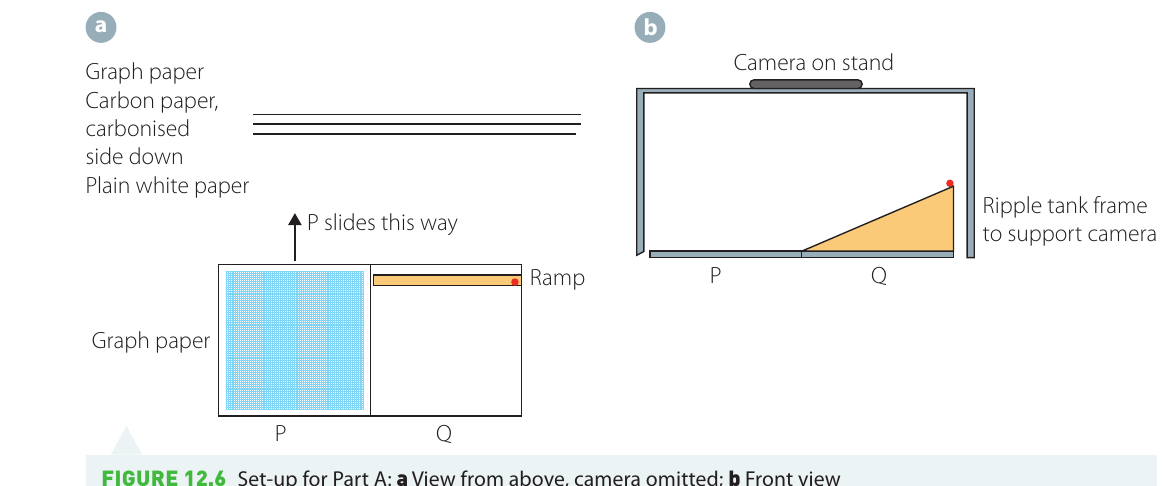
- Place carbon paper face down on a sheet of white paper.
- Place graph paper (facing up) on top to create a three-layer sandwich. The graph paper provides a coordinate grid.
- Tape this sandwich to one dissecting board (), with the carbonised side of the carbon paper facing down.
- Place a second dissecting board () next to .
- Secure the ramp on board .
- Position the camera frame (or ripple tank) over both boards and secure the camera to view the arrangement from above.
- Practice moving board at constant speed relative to board . This may take a few attempts to get smooth motion.
- While is moving at constant speed, release the ball bearing from the ramp. Try several different release heights.
- Video record the motion in each trial.
Part B: Accelerating frame of reference
- Place carbon paper face down on a sheet of white paper.
- Place graph paper (facing up) on top to form a sandwich.
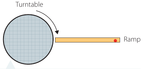
- Cut the sandwich to fit the circular turntable.
- Tape the sandwich to the turntable with the carbonised side down.
- Arrange the turntable and ramp so the ball bearing rolls smoothly from the ramp onto the turntable.
- Rotate the turntable at a constant rate.
- Release the ball bearing from the ramp at several different heights.
- Video record the motion in each trial.
Results
Identify each traced path on the paper and note which release height produced it.
Analysis of results
- From the video recording, determine (from the camera's frame of reference):
- a) The speed of the ball bearing
- b) The speed of board (Part A) or the turntable's rotation rate (Part B)
- Qualitatively compare the tracks for:
- a) Part A (inertial frame)
- b) Part B (accelerating frame)
- c) How do tracks from Part A differ from those in Part B?
- For Part A:
- a) Establish coordinate systems for both the camera frame and the moving board frame
- b) Create data tables showing position versus time for both coordinate systems
- c) Use the Galilean transformations to quantitatively compare measurements from the two frames
- Answer your inquiry question based on your observations.
Discussion questions
- How well did your results for Part A demonstrate the Galilean transformations? Did the mathematical predictions match your observations?
- The carbon paper records the motion as seen in the moving frame, while the camera records motion in the stationary frame. What differences did you observe between the path traced on the paper (moving frame) and the path seen in the video (stationary frame)?
- In Part B, the turntable is a non-inertial (accelerating) frame because it's rotating. The ball bearing appeared to follow a curved path on the rotating turntable. How can you explain this observation using Newton's laws?
Key Points to Remember
-
Inertial frames are reference frames that are either at rest or moving at constant velocity. Newton's laws apply accurately in these frames.
-
Non-inertial frames are accelerating or rotating frames. Observers in these frames experience additional apparent forces.
-
Galilean transformations relate position measurements in different inertial frames:
-
All inertial frames are equivalent - there is no privileged or "absolutely stationary" frame. The laws of physics work the same in all inertial frames.
-
Relative velocities add as vectors: . Always pay attention to the direction of motion when adding velocities.