Finite State Machines (AQA A-Level Computer Science): Revision Notes
Finite State Machines
What is a finite state machine?
A finite state machine (FSM) is a computational model that represents a device or system that can exist in a limited number of distinct states. At any given moment, the FSM is in exactly one state, and it can change to a different state based on the inputs it receives.
Think of an FSM as a system with memory that remembers its current status and responds to inputs by changing its state according to predefined rules. The term "finite" means there is a countable, limited number of possible states the machine can be in.
Real-world applications of FSMs
Finite state machines are everywhere in everyday life. They model any device or system where there is a predetermined sequence of steps and specific outcomes based on those steps. Common examples include:
- Automatic doors: The door can be either open or closed, and pressing a button causes it to switch between these states
- Vending machines: Moving through states as money is inserted and buttons are pressed
- Traffic lights: Cycling through red, amber, and green states
- Login systems: Progressing through username entry, password entry, and authenticated states
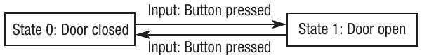
Simple Automated Door FSM
This simple automated door demonstrates a basic FSM with two states. When the button is pressed, the door toggles between closed and open states. The system always knows which state it's currently in and responds predictably to the button input.
Why FSMs are useful in computing
In practice, FSMs serve as powerful conceptual models for designing and describing computer systems. They are particularly valuable during the design phase because they force developers to think carefully about:
- Every possible state the system can be in
- All possible inputs that could be received
- How each input affects the current state
- What the system should do in each situation
FSMs in System Design
As a result, FSMs are commonly used to:
- Develop computer systems and software applications
- Design logic circuits and digital electronics
- Check the syntax of programming languages and validate code structure
- Model network protocols and communication systems
Representing finite state machines
There are two main ways to represent an FSM: state transition diagrams and state transition tables. Both show the same information but in different formats.
State transition diagrams
A state transition diagram is a visual representation of an FSM that uses circles and arrows to show how the system moves between states. This graphical format makes it easy to see at a glance how the machine behaves.
Components of state transition diagrams
States are represented by circles, with the state name or identifier (such as S0, S1, S2) written inside. Each circle represents a distinct condition or situation the system can be in.
Transitions are shown as arrows between states. Each arrow is labelled with the input that causes that transition to occur. The arrow points from the current state to the next state.
Start state is indicated by an arrow coming from nowhere pointing to the initial state where the FSM begins.
Accepting state (also called the goal state or final state) is shown as a double circle. This represents the state that indicates successful completion or acceptance. Not all FSMs require an accepting state.
Example: ticket machine
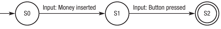
Vending Machine Sequential Process
This vending or ticket machine demonstrates a sequential process:
- S0: The initial state where the machine is waiting
- S1: Money has been inserted (intermediate state)
- S2: Button has been pressed (accepting state - ticket issued)
Notice how this FSM has sequence and memory. The button can only be pressed after money has been inserted, because you must be in state S1 before you can transition to S2. The machine "remembers" whether money has been put in or not.
Example: login authentication
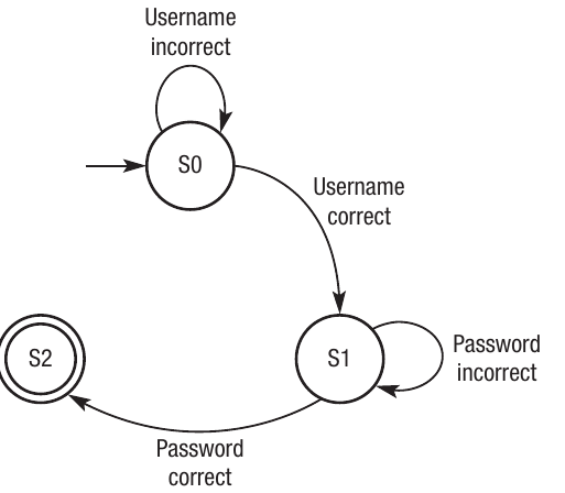
Login System with Loops
This login system shows a more complex behaviour with loops:
- S0: Initial state, waiting for username
- Self-loop: If username is incorrect, stay in S0
- Forward transition: If username is correct, move to S1
- S1: Username accepted, waiting for password
- Self-loop: If password is incorrect, stay in S1
- Forward transition: If password is correct, move to S2
- S2: Both credentials verified (accepting state - access granted)
This demonstrates dependency between states. The password cannot even be checked until the username has been accepted. Without the correct inputs at each stage, the system remains stuck and will not progress to the accepting state.
Example: syntax checking
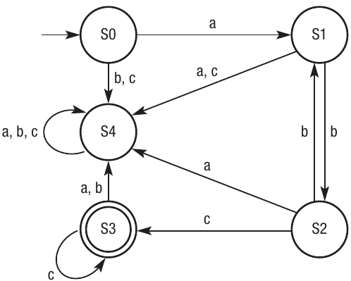
This more complex FSM shows how finite state machines can validate whether combinations of inputs (in this case, letters a, b, and c) follow certain rules. This type of FSM could represent checking whether a sequence of characters is valid according to programming language syntax rules.
Syntax Checking FSM Components
The diagram shows:
- S0 is the start state
- S3 is the accepting state (double circle)
- Multiple possible transitions between states based on different input letters
- Self-loops on some states (like S3 accepting 'c' repeatedly)
Validating Letter Sequences
Looking at this diagram, you can determine which letter sequences are acceptable:
- abc is acceptable: S0→S1→S2→S3
- abcc is acceptable: reaches S3 and stays there with more 'c' inputs
- acb is not acceptable: would end in S4, not the accepting state S3
- abca is not acceptable: S3 is the accepting state, so the final letter must be 'c' to end in S3
State transition tables
The same information shown in state transition diagrams can also be represented as a table. State transition tables provide a structured, tabular format showing the input, current state, and next state. Some people find tables easier to read than diagrams, especially for complex FSMs.
A state transition table has columns for:
- Input: The input or event that triggers the transition
- Current state: The state the machine is in before the input
- Next state: The state the machine moves to after processing the input
Example: automated door table
| Input | Current state | Next state |
|---|---|---|
| Button pressed | Door closed | Door open |
| Button pressed | Door open | Door closed |
This table represents the same automated door system shown earlier. Each row shows what happens when a specific input occurs in a specific state. The door toggles between open and closed whenever the button is pressed.
Example: ticket machine table
| Input | Current state | Next state |
|---|---|---|
| Money inserted | S0 | S1 |
| Button pressed | S1 | S2 |
This table shows the sequential progression through the ticket machine states. Notice that there is no row for "Button pressed" when in state S0, because that transition is not allowed - you must insert money first.
Example: syntax checking table
| Input | Current state | Next state |
|---|---|---|
| a | S0 | S1 |
| b | S1 | S2 |
| c | S1 | S4 |
| a | S1 | S4 |
| b | S2 | S1 |
| c | S2 | S3 |
| a | S2 | S4 |
| b | S0 | S4 |
| c | S0 | S4 |
| a | S3 | S4 |
| b | S3 | S4 |
| c | S3 | S3 |
| a | S4 | S4 |
| b | S4 | S4 |
| c | S4 | S4 |
Understanding Trap States
This comprehensive table shows all possible transitions for the syntax checking FSM. Notice how state S4 acts as a "trap state" where any further input keeps the machine in S4, indicating that the sequence has become invalid.
Finite state machines with outputs (A-level only)
Some finite state machines don't just change states - they also produce output values based on the inputs they receive. This special type of FSM is called a Mealy machine, named after George H. Mealy who invented it.
What is a Mealy machine?
A Mealy machine is a finite state machine where each transition can produce an output. The output depends on both the current state and the input received. This makes Mealy machines useful for systems that need to transform input data into output data.
Mealy machines were originally devised to define electronic circuits, and they are commonly used to express bitwise operations and data transformations in digital systems.
Example: shift cipher
A shift cipher is a simple encryption technique where letters are shifted by a fixed amount in the alphabet. For example, if we shift by 1, A becomes B, B becomes C, and so on.
Three-Letter Shift Cipher
This diagram shows a three-letter shift cipher where:
- A becomes D
- B becomes E
- C becomes F
The outputs (D, E, F) are shown next to the transitions, demonstrating how the input letters are transformed as the machine processes them.
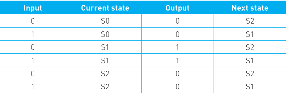
Example: right arithmetic shift
The Mealy machine performs a right arithmetic shift on binary values. This operation halves binary numbers by shifting bits to the right.
The state transition table for a Mealy machine includes an additional "Output" column:
| Input | Current state | Output | Next state |
|---|---|---|---|
| 0 | S0 | 0 | S2 |
| 1 | S0 | 0 | S1 |
| 0 | S1 | 1 | S2 |
| 1 | S1 | 1 | S1 |
| 0 | S2 | 0 | S2 |
| 1 | S2 | 0 | S1 |
In this table, you can see that each transition produces an output value (0 or 1) while also moving to a next state. This demonstrates how Mealy machines combine state transitions with data transformation.
Exam Tips for Finite State Machines
- When drawing state transition diagrams, always clearly mark the start state with an incoming arrow and any accepting states with double circles
- In exam questions, you may need to trace through a sequence of inputs and determine which state the FSM ends in
- Remember that state transition tables and diagrams contain the same information - you may find it easier to convert one to the other if you get stuck
- For Mealy machines, don't forget to include the output column in your state transition table
- Common mistakes include forgetting self-loops or missing transitions - make sure you account for all possible inputs from each state
Key Points to Remember
- A finite state machine (FSM) stores its current state and changes state based on inputs it receives
- FSMs are used as conceptual models for designing systems, checking syntax, and describing digital circuits
- State transition diagrams use circles for states and arrows for transitions, with double circles showing accepting states
- State transition tables show the same information in a structured format with columns for input, current state, and next state
- Mealy machines are special FSMs that produce outputs based on both the current state and input received
- FSMs must have a finite (countable) number of states and respond predictably to inputs based on predefined rules