Internal Hardware of a Computer (AQA A-Level Computer Science): Revision Notes
Internal Hardware of a Computer
Introduction to computers
A computer is any device or machine that processes data. When we think of computers, we often picture desktop PCs or laptops, but the definition is much broader. The term "computer" refers to any electronic or digital machine, which means it includes many devices you might not immediately think of as computers.
Computers are built using microscopic electronic circuits called microprocessors or chips. These chips can be programmed to control the device they're installed in. This means that computers come in many forms, including:
- Personal computers (PCs) and laptops
- Burglar alarms
- Microwave ovens
- Mobile phones
- Gaming consoles
When a computer chip is built into another device to control it, we call this an embedded system. The chip is "embedded" within the larger device. For example, a microwave oven contains an embedded computer system that controls the heating, timing, and display functions.
Embedded systems are everywhere in modern life. From the anti-lock braking system in your car to the smart thermostat in your home, embedded computers are silently controlling devices all around you. Understanding embedded systems is crucial because they represent the vast majority of computing devices in use today - far outnumbering traditional PCs and laptops.
Understanding that computers exist in so many forms is important for A-Level Computer Science. While we often use PCs as examples, the principles you learn apply to all types of computing devices.
The processor
The processor (also called the CPU - Central Processing Unit) is the brain of the computer. It's the component that performs all the computational work by carrying out instructions it receives from both hardware and software.
How the processor works
The processor's main job is to execute instructions in order to produce an output. Let me give you a simple example of how this works:
Worked Example: How a Keystroke Becomes a Character on Screen
When you press the 'A' key on your keyboard:
Step 1: An electrical signal travels either wirelessly or through a cable to the USB port at the back of your computer.
Step 2: This signal is routed through the processor, which recognises it as representing the letter 'A'.
Step 3: The processor then sends a signal to the monitor, which displays the letter on screen.
This simplified example shows the basic input-process-output cycle, though the actual process involves many more intermediate steps and instructions.
Of course, the actual process is much more complex than this. The processor carries out numerous invisible processes to display a single letter. It's also receiving instructions from many other programs and devices simultaneously.
Modern computers often have processors with multiple cores, and all of these cores need their actions coordinated to work together efficiently. A quad-core processor can execute four instruction streams simultaneously, significantly improving performance for multi-threaded applications.
Physical structure of the processor
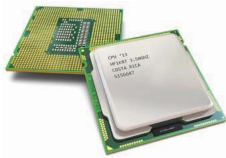
Physically, a processor consists of a thin slice of silicon approximately 2 centimetres square. Using microscopic manufacturing techniques, millions of tiny electronic components called transistors are implanted onto this silicon chip.
Microscopic wires called buses connect groups of transistors together. The transistors control the flow of electrical pulses that are timed via the computer's clock. These pulses of electricity represent different parts of the instruction the processor is carrying out. Each pulse is routed around the circuitry of the transistors at very high speeds.
Clock speed and performance
The speed at which the processor operates is determined by its clock speed. This is measured in Hertz (Hz), with modern processors typically operating at Gigahertz (GHz) speeds. For example, a 3 GHz processor can theoretically process (3000 million) instructions per second.
Generally speaking, the higher the clock speed, the faster the processor can execute instructions and the faster your computer will perform. However, clock speed isn't the only factor affecting performance. Other elements include:
- Number of processor cores
- Cache memory size
- Bus width
- Architecture design
Clock speed alone doesn't tell the whole story about processor performance. A modern dual-core processor running at 2.5 GHz might outperform an older single-core processor running at 3.5 GHz due to better architecture and parallel processing capabilities. This is why manufacturers now focus on multi-core designs rather than simply increasing clock speeds.
Manufacturers such as Intel and AMD continuously develop newer, faster chips. Each year brings improvements in processing power and efficiency.
Main memory
Memory is where the computer stores data and instructions for the processor to access. The processor needs to fetch both data and instructions from memory, decode them, and then execute them. This continuous process is known as the fetch-execute cycle, which is a fundamental principle in modern computing.
Memory acts as a medium of storage. Any new data created during program execution is stored back into memory. There are two main types of main memory: RAM and ROM.
RAM – Random Access Memory
RAM (Random Access Memory) is temporary storage space that the processor can access very quickly. This speed is crucial for applications like word processors and spreadsheets to run smoothly.
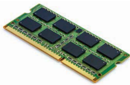
The speed of RAM becomes particularly noticeable when you're using your computer for graphics-intensive tasks or videos, which require more memory to refresh the graphics smoothly. Physically, RAM consists of a chip or series of chips containing millions of cells. Each cell stores data electronically and has its own unique address. Each cell can contain either an instruction or a piece of data.
How RAM works
The processor can access RAM cells in any order by referencing their addresses - hence the name "Random Access". This means cells can be accessed randomly rather than sequentially, and because they're electronic, they can be accessed very quickly.
However, RAM has one critical characteristic: it's volatile. This means that when you turn your computer off, all the contents of RAM are lost. This is why you need to save your work regularly.
Never rely on RAM alone for your work! Because RAM is volatile, any unsaved work will be permanently lost if your computer crashes, loses power, or is turned off. Always save your documents frequently to non-volatile storage (like your hard drive or SSD) to prevent data loss.
RAM in practice
Whenever you run a program on your computer, the entire program (or parts of it) loads into RAM. The more RAM you have, the more applications you can have loaded and running simultaneously.
Worked Example: Using a Spreadsheet
Step 1: Opening the file When you open a spreadsheet file, both the spreadsheet application and the data file are loaded into RAM from your hard drive.
Step 2: Working with data When you create formulas in the spreadsheet, these are temporarily stored in RAM as you work. Any calculations you perform happen in RAM for fast access.
Step 3: Saving your work If you save the file, the contents are written from RAM to your hard drive (non-volatile storage).
Step 4: Closing without saving If you turn off the computer without saving, the spreadsheet closes and your work is lost because RAM is cleared when power is removed.
RAM capacity over time
Memory technology has advanced significantly over the years:
- 1997: 32 MB was fairly standard
- 2003: 512 MB became standard
- 2014: 4-8 GB became the standard range for laptops and desktops
Software manufacturers continuously develop programs that take advantage of increased memory capacity. You may have noticed that certain programs won't run on machines that don't have enough RAM installed.
The trend of increasing RAM capacity continues today, with many modern systems featuring 16 GB or even 32 GB of RAM as standard. This increase supports more demanding applications like video editing, 3D modeling, and running multiple virtual machines simultaneously. Gaming systems often require even more RAM to ensure smooth performance with modern, graphics-intensive games.
ROM – Read Only Memory
ROM (Read Only Memory) is another method of storing data and instructions, but it works quite differently from RAM. The key characteristics of ROM are:
- Non-volatile: Contents are not lost when you switch off the computer
- Read-only: Users cannot alter the contents (in traditional ROM)
- Permanent: Contents are programmed by the manufacturer
It's important to note that programmable ROM does exist (used in memory sticks and other devices), but the traditional ROM used inside a PC is read-only. Don't confuse modern programmable flash memory with the ROM chips that store your computer's BIOS - they serve different purposes.
ROM in practice
In a PC, ROM stores a limited number of instructions relating to the computer's startup process. These settings are stored in the BIOS (Basic Input/Output System).
When you switch on your computer, it carries out several instructions automatically:
- Checks which hardware devices are plugged in
- Loads parts of the operating system
- Performs other startup routines
All of these instructions are stored in ROM and are programmed into it by the computer's manufacturer. The BIOS acts as firmware that bridges the hardware and operating system during the boot process.
Addressable memory
Memory consists of millions of addressable cells. The various instructions and data that make up a program are stored across many of these cells. Each address uniquely identifies a particular cell.
The processor's job is to retrieve each instruction and data item from memory and carry out the instructions in a sequential manner. This is the essence of the fetch-execute cycle.
Memory organisation
Memory is organised systematically using addresses. This allows different programs to be stored in different parts (blocks) of memory. For example:
- A block of memory addresses might be allocated for the operating system
- Another block for application software
- Another for library programs
- And so on
This systematic organisation means the processor can find the data and instructions it needs much more quickly than if programs were stored completely randomly.
Memory maps
A memory map can be produced to show which programs are stored at which addresses. Memory addresses are normally displayed in hexadecimal format rather than binary, as the hexadecimal version is shorter and easier to read.
Worked Example: A Basic Memory Map
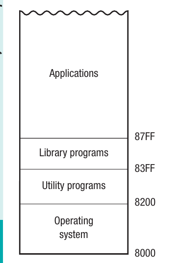
Here's how a simple memory map might be organized:
| Address Range | Contents |
|---|---|
| 8000-8200 | Operating system |
| 8200-83FF | Utility programs |
| 83FF-87FF | Library programs |
| 87FF onwards | Applications |
This logical structure allows the processor to locate and access different types of software efficiently. When the processor needs to access the operating system, it knows to look in the 8000-8200 range. When it needs to run an application, it looks from 87FF onwards.
Buses
Buses are groups of parallel microscopic wires that connect the processor to the various input and output controllers in the computer. They're also used to connect the internal components of a microprocessor (called registers - covered in Chapter 33) and to connect the microprocessor to memory.
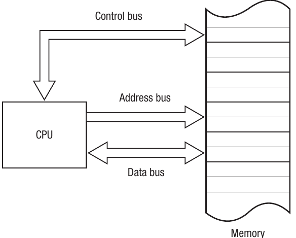
Think of buses as highways that carry information around the computer system. There are three types of bus: data, address, and control.
Data bus
The data bus transfers data between the processor and memory. Instructions and data that make up a computer program pass back and forth between the processor and memory as the program runs.
The data bus carries data in both directions to and from memory and to and from the I/O controllers. This means the data bus is bi-directional or two-way.
Bus width
The instructions and data held in memory vary in size. Each memory cell has a width measured in bits. For example, a cell might have a width of 32 bits.
The amount of data that can be passed along the data bus depends on how many wires make up the bus. An 8-bit data bus has eight wires. Since each wire can only carry either a 0 or a 1, an 8-bit bus can transmit any item of data that can be represented using combinations, which equals 256 different patterns.
As we learned in earlier sections, these patterns can represent text, numbers, sound, graphics, or instructions.
The relationship between bus width and data capacity is exponential. Each additional wire doubles the number of possible bit patterns:
- 8-bit bus: patterns
- 16-bit bus: patterns
- 32-bit bus: patterns
- 64-bit bus: patterns
This exponential growth explains why wider buses dramatically improve performance.
Data transmission
When large data items need to be transmitted, the data must be split into smaller parts and sent one after the other. The greater the width of the data bus (in terms of wires), the more data can be transmitted in one pulse of the clock.
Consequently, the size of the data bus is a key factor in determining the overall speed and performance of the computer. At the time of writing, 32-bit and 64-bit buses are standard.
The data bus width is usually the same as the word length of the processor and the memory word length. The word length refers to the number of bits that can be addressed, transferred, or manipulated as one unit.
Address bus
The address bus only goes in one direction - from the processor into memory. It's used to specify a physical address in memory so that the data bus can access the required information.
All the instructions and data that a processor needs to carry out a task are stored in memory. Every memory location has an address. The processor carries out instructions one after another, and the address bus carries the memory address of the next instruction or data item.
The address bus is therefore used to access anything stored in memory, not just instructions. It points to where in memory the processor needs to look next.
Address bus size and memory capacity
The size of the address bus is also measured in bits and represents the amount of memory that is addressable. An 8-bit bus would only provide 256 directly addressable memory cells ().
This means a program could only consist of a maximum of 256 separate instructions and data items. If we assume each memory address can store 8 bits (one byte) of data, we would have only 256 bytes of memory available - completely useless on modern computers!
Worked Example: Calculating Addressable Memory
Let's calculate the addressable memory for different address bus sizes:
Example 1: 24-bit address bus
- Formula: memory locations
- Calculation: bytes
- Result: 16 MB of addressable memory
Example 2: 32-bit address bus (common for most PCs)
- Formula: memory locations
- Calculation: bytes
- Result: 4 GB of addressable memory
Example 3: 64-bit address bus
- Formula: memory locations
- Calculation: bytes
- Result: Approximately 16.8 million terabytes (in theory)
Key insight: Each additional wire in the address bus doubles the addressable memory capacity!
Control bus
The control bus is a bi-directional bus that sends control signals to the registers, the data bus, and the address bus.
There's a lot of data flowing around the processor:
- Between the processor and memory
- Between the processor and input/output controllers
- Data buses sending data to and from memory
- Address buses sending addresses only to memory
The job of the control bus is to ensure that the correct data travels to the right place at the right time. This involves:
- Synchronising signals
- Controlling access to the data and address buses (which are being shared by multiple devices)
Control bus functions
Examples of control signals include:
- Direction control: A signal on the control bus dictates the direction of data transmission through the data bus
- Read/Write indication: Signals indicate whether the processor is reading from or writing to an I/O port
- Clock pulses: The control bus transmits the pulses delivered by the system's clock to coordinate all operations
The control bus acts like a traffic controller at a busy intersection. Without it, data could collide on the buses or arrive at the wrong destination. The control bus's coordination signals ensure that all components work together in perfect synchronisation, preventing data corruption and system crashes.
The control bus is essential for coordinating all the different data movements happening simultaneously within the computer.
Input/Output (I/O) controllers
In addition to the direct link between the processor and main memory, the processor also receives and sends instructions and data to various input and output devices connected to the computer. Basic I/O devices include:
- Keyboard
- Monitor
- Mouse
- Printer
Modern computer systems typically include many other devices as well.
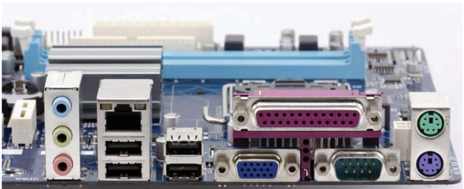
Physical connections
Physically, I/O devices connect via I/O ports on your computer, usually USB ports. The ports are physical connections that allow I/O devices to be plugged in. For example:
- The printer plugs into a USB port
- Signals pass in both directions through the printer cable
- The signals travel via the port and through the processor to send and receive instructions
How I/O controllers work
Inside the computer, the data buses carry signals to and from the processor. The processor works with I/O devices in the same way it works with memory - sending and receiving data. However, the processor doesn't communicate directly with the I/O devices. Instead, there's an interface called an I/O controller.
Controller structure
Controllers consist of their own circuitry that handles the data flowing between the processor and the device. Every device has its own controller, which allows new devices to be connected to the processor at any time. As a minimum, a typical computer will have:
- A monitor controller
- A mouse controller
- A keyboard controller
- A hard disk controller
Why I/O controllers are necessary
I/O controllers serve several critical functions:
Three Critical Roles of I/O Controllers:
1. Signal translation A key feature of an I/O controller is that it translates signals from the device into the format required by the processor. There are many different devices and many different types of processors. The I/O controller provides the flexibility to add new devices without having to redesign the processor.
2. Speed buffering I/O devices respond relatively slowly compared to the speed at which a processor can work. The I/O controller buffers (temporarily stores) data being sent between the processor and the device. This means the processor doesn't have to wait for the slower individual device to respond - it can continue working on other tasks.
3. Device flexibility Controllers allow you to add new peripherals to your computer without needing to modify the processor. The controller acts as an intermediary that handles the specific communication requirements of each device.
Worked Example: Printing a Document
Here's how I/O controllers work when you print a document:
Step 1: You send the print command The application sends the document data to the processor.
Step 2: Processor to printer controller The processor sends the print data to the printer controller at high speed (matching the processor's speed).
Step 3: Controller buffers the data The printer controller stores the entire document in its buffer memory, allowing the processor to move on to other tasks immediately.
Step 4: Controller manages the printer The controller sends data to the printer at the printer's much slower speed, translating the processor's signals into commands the printer understands.
Result: You can continue working on your computer while the document prints, because the processor isn't waiting for the slow printer - the controller handles that communication.
Von Neumann and Harvard architectures
In previous sections, we established that a program is a series of instructions that the processor carries out. Programs also require data on which to perform these instructions.
When a program runs, it loads into main memory. In simple terms, this means that the instructions and data that make up the program are both stored in main memory and must both pass through the same bus (the data bus) in and out of memory.
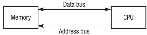
Von Neumann architecture
The early computers that used this concept were known as "von Neumann" machines, named after the man who first invented this technique in the 1940s. Most modern PCs still use this technique and are therefore von Neumann machines.
The word "architecture" is widely used in computing and usually refers to the way something is built. For example, a microprocessor has an architecture that refers to how the chip is built. The von Neumann method of building computers is therefore often referred to as von Neumann architecture.
Key characteristics of von Neumann architecture
- Instructions and data are stored in the same memory
- Both instructions and data are accessed via the same buses
- The processor fetches one instruction at a time from memory
- Instructions are executed sequentially (one after another)
- Most general-purpose PCs use this architecture
The von Neumann architecture creates what's known as the "von Neumann bottleneck." Because instructions and data share the same bus, they cannot be fetched simultaneously. This can limit performance, as the processor must wait for the bus to be available. Despite this limitation, the simplicity and flexibility of this architecture have made it the standard for general-purpose computing.
Harvard architecture
An alternative method of building chips is the Harvard architecture. The key difference between Harvard and von Neumann is that separate buses are used for data and instructions, and these buses address different parts of memory.
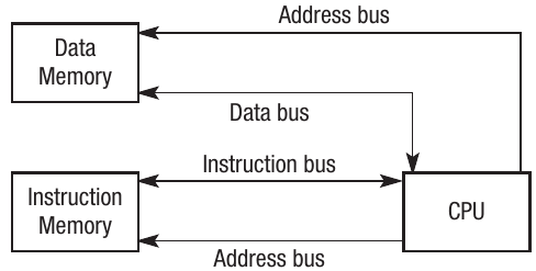
Rather than storing data and instructions in the same memory and passing them through the same bus, there are two separate buses addressing two different memories:
- One memory and bus system for data
- Another memory and bus system for instructions
Advantages of Harvard architecture
The main advantage is that instructions and data are handled more quickly because they don't have to share the same bus. Therefore, a program running on Harvard architecture can be executed faster and more efficiently.
Choosing the Right Architecture
The choice between von Neumann and Harvard architecture depends on the application:
Use von Neumann when:
- You need flexibility to run different types of programs
- General-purpose computing is required
- The program-to-run isn't known in advance
Use Harvard when:
- The device has a specific, dedicated purpose
- Speed and efficiency are critical
- Power consumption must be minimized
- The program is embedded and doesn't change
Where Harvard architecture is used
Harvard architecture is widely used on embedded computer systems such as:
- Mobile phones
- Burglar alarms
- Digital cameras
- Washing machines
These devices have a specific use rather than being general-purpose computers like PCs.
Digital Signal Processing (DSP)
Many embedded devices use a technique called Digital Signal Processing (DSP). The idea of DSP is to take continuous real-world data (such as audio or video data) and compress it to enable faster processing.
Chips optimised for DSP tend to have much lower power requirements, making them ideal for applications such as mobile phones where power consumption is critical. Battery life is a major consideration in portable devices, so the efficiency of Harvard architecture combined with DSP makes this combination popular for embedded systems.
Digital Signal Processing is essential in modern mobile devices. When you make a phone call, DSP compresses your voice data in real-time, reducing the bandwidth needed for transmission. When you listen to music on your phone, DSP decompresses the audio file efficiently. The combination of Harvard architecture and DSP enables these devices to perform complex operations while maintaining long battery life.
Remember!
Key Points to Remember:
-
The processor is the brain of the computer that executes all instructions by following the fetch-execute cycle. Clock speed and the number of cores affect its performance.
-
RAM is volatile temporary storage accessed quickly by the processor, while ROM is non-volatile permanent storage containing startup instructions like the BIOS.
-
Three types of buses connect computer components: the data bus (bi-directional) carries data, the address bus (uni-directional) specifies memory locations, and the control bus (bi-directional) coordinates all operations.
-
I/O controllers act as intermediaries between the processor and external devices, translating signals, buffering data due to speed differences, and allowing flexible device connections without processor redesign.
-
Von Neumann architecture stores instructions and data in the same memory accessed via the same buses (used in most PCs), while Harvard architecture uses separate memory and buses for instructions and data (used in embedded systems for faster, more efficient processing).