The Processor Instruction Set and Addressing Modes (AQA A-Level Computer Science): Revision Notes
The Processor Instruction Set and Addressing Modes
Introduction
When we write programs, we typically use high-level languages like Python or Java. However, the processor cannot directly understand these languages. At the lowest level, the processor works with machine code, which consists of patterns of binary digits (0s and 1s). Assembly language sits between high-level languages and machine code, providing a more human-readable way to write instructions that closely correspond to machine code operations.
Assembly language uses mnemonics - short, memorable codes that represent specific processor operations. Rather than writing strings of 0s and 1s, programmers can use these mnemonics to create programs that are easier to read and understand, whilst still maintaining close control over the processor's operations.
Think of the language hierarchy as a pyramid: high-level languages like Python sit at the top (most human-readable), assembly language sits in the middle (using mnemonics for readability), and machine code sits at the bottom (pure binary that the processor directly executes).
What is an instruction set?
An instruction set is a collection of binary patterns that a specific processor recognises as valid commands. Each processor has its own instruction set, which defines all the operations that processor can perform. Think of it as the processor's vocabulary - the complete set of "words" it understands.
Instruction sets are processor-specific!
Each processor family has its own unique instruction set. Code written for an ARM processor won't work on an Intel x86 processor without modification, because they speak different "languages" at the machine level.
Instruction sets are classified into two main types:
- RISC (Reduced Instruction Set Computer): Uses a smaller set of simple instructions that execute quickly
- CISC (Complex Instruction Set Computer): Uses a larger set of more complex instructions that can perform multiple operations
The instruction set determines what operations are available and how they are encoded in binary form.
Structure of assembly language instructions
Every assembly language instruction consists of four main components, though not all components are required for every instruction:
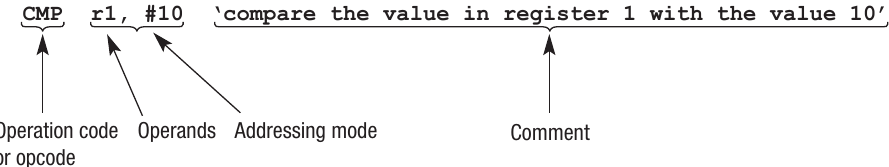
1. Operation code (opcode)
The opcode specifies what operation the processor should perform. It is represented by a mnemonic, typically consisting of one to four characters. The mnemonic uses letters that help explain what the instruction does. For example:
- ADD means addition
- MOV means move data
- CMP means compare values
2. Operands
Operands specify the data or memory locations that the operation will work with. The number of operands varies depending on the operation:
- Some operations require no operands
- Others need one operand
- Many require two operands (such as specifying a source and destination)
For example, in CMP r1, #10:
- The first operand (r1) identifies the register to be accessed
- The second operand (#10) provides the data to compare with
With the ARM6 architecture (and many others), the first operand typically refers to a register. This is a common convention that makes reading assembly code more predictable.
3. Addressing mode
The addressing mode tells the processor how to interpret the operand. A special symbol indicates the addressing mode being used:
- The # symbol indicates immediate addressing, meaning the value that follows is the actual data to be used
- Without the # symbol, direct addressing is used, meaning the value represents a memory address or register number
4. Comments
Comments are optional but highly recommended. They explain what the instruction does in plain language, making assembly programs much easier to understand and maintain. Since assembly programs can become very long and complex, good commenting practice is essential.
Machine code representation
When assembly language is converted to machine code, the instruction is encoded as a fixed pattern of binary bits. The processor allocates a specific number of bits to each component of the instruction.
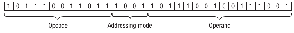
Understanding bit allocation
For example, in a 32-bit instruction:
- 12 bits might be allocated for the opcode
- 4 bits for the addressing mode
- 16 bits for the operand
Different instruction sets may use fixed or variable bit allocations. Some systems fix the number of bits for each component, whilst others allow the allocations to vary. Increasing the number of bits available means a wider range of opcodes and operands can be represented within the instruction set.
Worked example: Converting high-level code to assembly
Let's see how a simple if-else statement in a high-level language translates to assembly language. Consider this pseudocode:
if y = 10 then
    x ← 9
else
    y ← y + 1
endif
Worked Example: Converting If-Else to ARM Assembly
Using the ARM6 processor instruction set, let's break down what each instruction does:
- CMP r1, #10 - Compares the value stored in register 1 (which holds variable y) with the immediate value 10
- BNE else - Branches to the label "else" if the values are Not Equal
- MOV r2, #9 - Moves the immediate value 9 into register 2 (which holds variable x)
- B endif - Branches unconditionally to the "endif" label, skipping the else section
- else - Label marking the start of the else block
- ADD r1, r1, #1 - Adds the immediate value 1 to the value already in register 1 (y = y + 1)
- endif - Label marking the end of the if-else structure
Notice how registers are used to store the variables: register 1 (r1) holds the value of y, and register 2 (r2) holds the value of x.
Addressing modes
When the processor needs to access data, it must know where that data is located in memory. The addressing mode tells the processor how to interpret the operand - whether it represents the actual data or the location of the data.
You can visualise memory as a vast collection of storage locations, each with its own unique address. Just like houses on a street each have a unique address, each memory location has a unique number that identifies it.
Immediate addressing
Immediate addressing means the operand contains the actual data value you want to use. The # symbol indicates immediate addressing.
For example:
- MOV r1, #10 moves the value 10 directly into register 1
The processor doesn't need to look anywhere else - the data (10) is immediately available within the instruction itself. This is fast and efficient when you know the exact value you need.
Direct addressing
Direct addressing means the operand contains the address of a memory location where the data is stored. Without the # symbol, the processor interprets the operand as a memory address.
For example:
- LDR r1, 100 loads into register 1 the data stored at memory location 100
The processor must access memory location 100 to retrieve the data stored there, then place that data into register 1. The operand (100) is not the data itself, but rather the address where the data can be found.
Key difference
The # Symbol Makes All the Difference!
- Immediate addressing (#10): "Use this value" - the operand IS the data
- Direct addressing (100): "Go to this address and get the value there" - the operand is a LOCATION
Remember: # means the number itself, no # means go to that address
Types of operation codes
Operation codes (opcodes) can be grouped into four main categories based on their function: data transfer, arithmetic, logical, and branch operations.
Data transfer operations
Data transfer operations move data between different locations - typically between registers and main memory. These are fundamental operations that enable the processor to access and store data.
Common data transfer instructions include:
- MOV (Move): Copies a value from one location to another
- STR (Store): Stores the contents of a register into a memory location
- LDR (Load): Loads data from a memory location into a register
For example:
- MOV r1, #25 copies the value 25 into register 1
- STR r1, 200 stores the contents of register 1 into memory location 200
- LDR r1, 200 loads the data from memory location 200 into register 1
Arithmetic operations
Arithmetic operations perform mathematical calculations. Beyond the four basic operations (add, subtract, multiply, divide), this category includes several other useful functions:
- ADD: Addition
- SUB: Subtraction
- Increment: Increase a value by one
- Decrement: Decrease a value by one
- Compare: Compare two values (affects status flags but doesn't store a result)
- Shift instructions: Move bits left or right within a register
The Status Register
The status register records important information about arithmetic results, such as:
- Whether an overflow error occurred
- Whether the result is zero
- Whether the result is negative
This information is crucial for conditional branching and error detection.
Shift instructions
Shift instructions are particularly useful operations that move bits within a register either left or right. They can be used to extract individual bits or perform efficient multiplication/division by powers of 2.
Worked Example: Shift Right Operation
Consider the bit pattern:
1 0 1 1 1 0 0 1
A shift right operation moves all bits one position to the right:
0 1 0 1 1 1 0 0 ➞ 1
The rightmost bit (1) falls off the end and is placed in the carry bit. A 0 is placed in the leftmost position. This is called a logical shift right.
Alternatively, a rotate right operation would take the bit from one end and place it at the other end, so the least significant bit (LSB) becomes the most significant bit (MSB), and all other bits shift one position to the right.
Logical operations
Logical operations perform bitwise comparisons and manipulations. These operations work on individual bits within binary numbers, comparing corresponding bits in two values.
The main logical operations are:
AND operation
- Compares each bit in two binary numbers
- Returns 1 only if BOTH bits are 1
- Otherwise returns 0
- Useful for masking (selecting specific bits)
Example:
    0011
AND 0010
  = 0010
OR operation
- Compares each bit in two binary numbers
- Returns 1 if EITHER or BOTH bits are 1
- Returns 0 only if both bits are 0
- Useful for setting specific bits to 1
Example:
    0011
OR  0010
  = 0011
NOT operation
- Inverts each bit (1 becomes 0, 0 becomes 1)
- Produces the two's complement
- Example: NOT 0011 = 1100 (in binary, +3 becomes -4 in two's complement)
XOR operation
- Returns 1 if the bits are DIFFERENT
- Returns 0 if the bits are the SAME
- Useful for comparing values
- XORing a number with itself always produces 0
Example:
    0011
XOR 0011
  = 0000
Practical Applications of Logical Operations
These operations are invaluable for bit manipulation tasks, such as:
- Creating masks to extract specific bits
- Setting or clearing individual flags
- Checking parity bits
- Performing efficient comparisons
- Encryption and data manipulation
Logical operations are the foundation of many low-level programming techniques and hardware control mechanisms.
Branch operations
Branch operations enable non-linear program execution by allowing the processor to jump from one part of the program to another. Without branching, all programs would be strictly sequential, making it impossible to create loops or conditional structures like if-else statements.
Unconditional branches
- The B (Branch) instruction performs an unconditional jump
- The processor always jumps to the specified label, regardless of any conditions
- Format: B
Conditional branches
- These branches only execute if a specific condition is met
- The condition is based on the result of the previous comparison operation
- Common conditional branches include:
- BNE - Branch if Not Equal
- BEQ - Branch if Equal
- BGT - Branch if Greater Than
- BLT - Branch if Less Than
The result of the most recent comparison (using the CMP instruction) determines whether the branch is taken. Labels mark the destination points in the code where branches can jump to.
Branch Operations Enable All Control Structures
All the complex control structures available in high-level languages (such as loops, switch statements, and nested conditions) can be constructed using these basic branch operations. High-level languages hide this complexity, but underneath they all rely on these fundamental branching mechanisms.
When you write a while loop or an if-else statement in Python, the compiler or interpreter translates it into conditional and unconditional branch instructions at the machine level.
ARM processor instruction set reference
The following table summarises some common instructions from the ARM processor instruction set:
| Instruction | Description |
|---|---|
| LDR Rd, | Load the value stored in the memory location specified by |
| STR Rd, | Store the value that is in register d into the memory location specified by |
| ADD Rd, Rn, | Add the value specified in |
| SUB Rd, Rn, | Subtract the value specified by |
| MOV Rd, | Copy the value specified by |
| CMP Rn, | Compare the value stored in register n with the value specified by |
| B | Always branch to the instruction at position in the program |
| B | Conditionally branch to the instruction at position if the last comparison met the criteria specified by |
| AND Rd, Rn, | Perform a bitwise logical AND operation between the value in register n and the value specified by |
| ORR Rd, Rn, | Perform a bitwise logical OR operation between the value in register n and the value specified by |
| EOR Rd, Rn, | Perform a bitwise logical exclusive or (XOR) operation between the value in register n and the value specified by |
| MVN Rd, | Perform a bitwise logical NOT operation on the value specified by |
| LSL Rd, Rn, | Logically shift left the value stored in register n by the number of bits specified by |
| LSR Rd, Rn, | Logically shift right the value stored in register n by the number of bits specified by |
| HALT | Stops the execution of the program |
Interpreting operands
The
- # symbol followed by a number uses immediate addressing (the actual value)
- Example: #25 means use the decimal value 25
- R followed by a number uses register addressing (the value in a register)
- Example: R6 means use the value currently stored in register 6
Exam Tips for Assembly Language
- Always check whether an operand uses the # symbol - this tells you if it's immediate or direct addressing
- Remember that in ARM architecture, the first operand typically refers to a register
- When writing assembly code, use clear labels and comments to make your logic easy to follow
- Be familiar with the difference between unconditional branches (B) and conditional branches (B
) - Understand that shift operations can be used for efficient multiplication and division by powers of 2
- Know that logical operations work bit-by-bit, comparing corresponding positions in two binary numbers
- Practice converting simple high-level structures (if-else, loops) into assembly language
Key Points to Remember:
-
An instruction set is the complete collection of binary patterns that a specific processor recognises as valid commands, along with their meanings
-
Assembly language instructions consist of four parts: opcode (the operation), operands (the data/addresses), addressing mode (how to interpret operands), and optional comments
-
Immediate addressing (using #) means the operand contains the actual data value to use
-
Direct addressing (no #) means the operand contains a memory address where the data is located
-
Four categories of operations: data transfer (moving data), arithmetic (calculations), logical (bit manipulation), and branch (changing program flow)
-
Conditional branches depend on the result of the previous comparison and enable decision-making structures in programs
-
Each processor has its own instruction set - what works on ARM won't necessarily work on other processor architectures