Potential divider (AQA A-Level Physics): Revision Notes
5.1.5 Potential divider
Potential Divider Basics
A potential divider is a circuit containing multiple resistors in series across a voltage source. Its main purpose is to produce a specific fraction of the source voltage as an output, which remains stable.
- By altering the resistance values within the circuit, the potential divider can vary the output potential difference.
- One common approach is to use a variable resistor within the potential divider circuit. Adjusting this resistor changes the output voltage by modifying the current and, consequently, the potential difference across each component.
Potential Divider Formula:
The output potential difference, , across a resistor in a series arrangement with another resistor is given by:
Where:
- is the input (source) voltage.
- and are the resistances of the resistors in series.
Example: Using a Variable Resistor
Consider a potential divider with resistors and . If a variable resistor is used in place of , adjusting 's resistance allows control over the output voltage across :
- Increasing decreases the current, reducing across .
- Decreasing increases the current, raising . This principle is useful for creating circuits with adjustable output voltages.
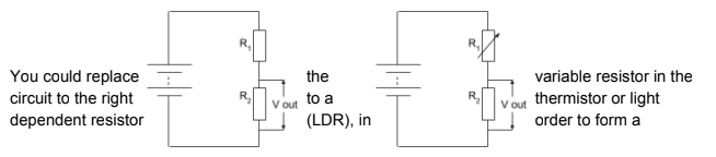
Using Light-Dependent Resistors (LDRs) and Thermistors in Potential Dividers
Potential dividers can be adapted for sensing applications by using a light-dependent resistor (LDR) or a thermistor:
-
LDR (Light Dependent Resistor): Its resistance decreases as light intensity increases.
-
Thermistor: Its resistance changes with temperature (in most cases, decreases as temperature rises). When an LDR or thermistor is used in a potential divider circuit:
-
Changes in light intensity or temperature directly affect the resistance of the LDR or thermistor.
-
This in turn changes the output voltage, which can be used to trigger specific responses in a circuit (e.g., turning on a light when it gets dark).
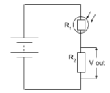
Example Circuit with LDR
In the example below, the circuit uses an LDR to adjust the output voltage based on light levels:
- When light intensity decreases, the resistance of the LDR increases.
- This causes the voltage across the LDR to increase, reducing .
- This change can be used to trigger a circuit action, such as activating a light bulb when the room gets dark. If you want the opposite effect (increasing with decreasing light intensity), switch the positions of and the LDR.
Applications of Potential Dividers in Real-World Circuits
- Light Sensors: Automatically turn on street lamps as it gets dark.
- Temperature Sensors: Use thermistors to regulate heating systems. By carefully choosing components and their arrangement, potential dividers provide an effective way to control and adjust voltage outputs in response to environmental changes, making them essential in various automatic control systems.
Key Takeaways
- Potential dividers split an input voltage to provide a specific output voltage.
- Variable resistors can be used within a potential divider to adjust the output voltage.
- LDRs and thermistors allow potential dividers to respond to light and temperature changes.
- Real-world applications include automatic lighting and temperature-based control circuits.