Computers & CNC Machining (Junior Cert Engineering): Revision Notes
Computers & CNC Machining
Use of computers in technology
Computers have become essential tools in modern manufacturing and engineering. They are widely used across many applications including:
- Machine control - Operating and monitoring manufacturing equipment
- Robot control - Programming automated systems for precision tasks
- Design work - Creating technical drawings and 3D models
- Documentation - Producing technical drawings and printed reports
- Information access - Researching specifications and technical data
- Simulation - Testing operations virtually before actual production
Computer hardware and software fundamentals
Understanding the basic components of computer systems is crucial for CNC applications.
Hardware vs software
Hardware refers to the physical components that make up a computer system. Software consists of the programmes, languages and procedures that control these systems.
Computer systems work using three types of components:
- Input devices - Send data into the system
- Processing unit - Handles calculations and controls operations
- Output devices - Display or produce results
Central processing unit (CPU)
The CPU acts as the "brain" of any computerised system. It contains the main electronic chips that perform all calculations, carry out instructions, and transfer data between different system components.
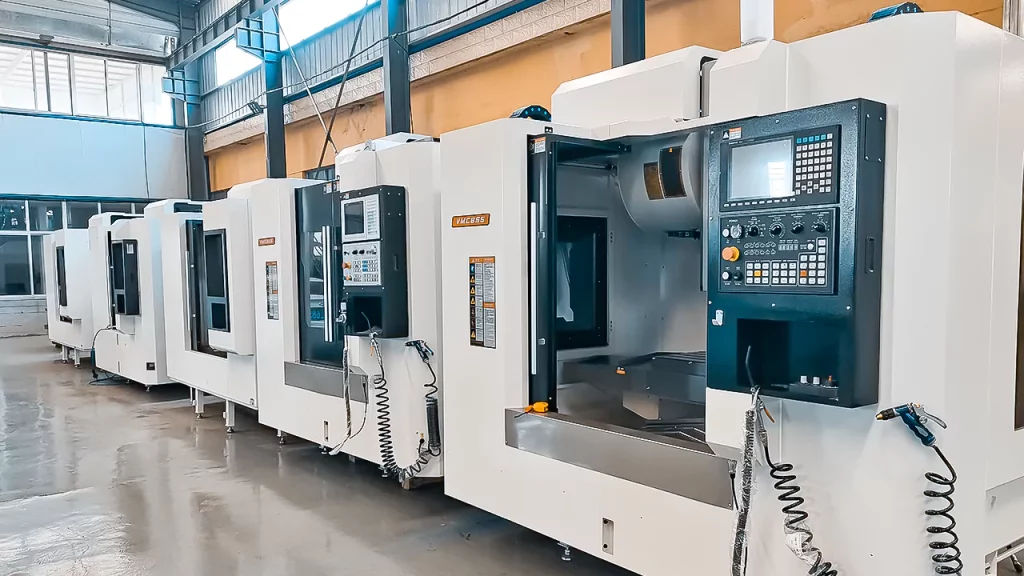
CNC machining fundamentals
CNC stands for Computer Numerical Control. These machines use computerised systems to control manufacturing operations with high precision and repeatability.
CAD and CAM systems
Two essential technologies work together in CNC manufacturing:
CAD (Computer-Aided Design) - Software used to create detailed technical drawings and 3D models of components
CAM (Computer-Aided Manufacturing) - Software that converts CAD drawings into machine-readable programmes that control the actual manufacturing process
The CAM programme contains all the instructions needed to operate a CNC machine and produce the desired component. Once written, the same programme can manufacture identical parts repeatedly.
CNC lathework and turning
CNC lathes are controlled entirely by computer programmes. These programmes can be written manually or generated automatically using CAD/CAM systems, which is typically faster and more efficient.
Stepper motors provide precise movement control for the machine slides. Many modern CNC lathes include tool turrets that automatically position different cutting tools as needed.
Advantages and disadvantages of CNC turning
Key advantages include:
- Fast automatic operation with consistent results
- High accuracy and repeatability
- Enhanced safety through enclosed working areas
- Ability to create complex shapes
- Programmes can be tested through simulation
- Same programme produces identical parts
Main disadvantages are:
- Settings can be disrupted easily
- High initial investment costs
- Careful tool management required to prevent collisions
CNC programming concepts
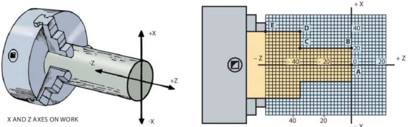
Coordinate systems
CNC lathes use X and Z coordinate systems to define tool positions:
- X coordinates - Distances perpendicular to the laith centreline (diameters)
- Z coordinates - Distances parallel to the centreline (length)
Even though measurements show radius values, X coordinates represent full diameters for programming purposes.
G codes and M codes
CNC programmes use two main types of instruction codes:
G codes control tool movements:
- G00 - Rapid movement between points
- G01 - Straight line cutting at controlled feed rate
- G02 - Clockwise circular movement
- G03 - Counter-clockwise circular movement
M codes handle machine functions:
- M02 - End of programme
- M03 - Start spindle clockwise rotation
- M04 - Start spindle counter-clockwise rotation
- M05 - Stop spindle
- M06 - Tool change command
Canned cycles
Canned cycles allow multiple repetitive operations to be programmed with a single command line. This simplifies programming when creating features like multiple cuts to reduce a diameter.
Dimensioning methods
Two approaches are used for programming dimensions:
Incremental dimensioning - Each dimension is measured from the previous position Absolute dimensioning - All dimensions are measured from a fixed reference point (datum)
Using a CAD/CAM system
Creating components using CAD/CAM involves several key steps:
Setting up the project
The raw material (called a billet) must be defined with:
- Component details and specifications
- Billet dimensions (outside diameter, inside diameter if hollow, length, hole depth)
- Programme name and file location
CAD interface and tools
The CAD software provides a grid-based drawing environment with various tools for creating technical drawings:

Essential drawing tools include:
- Straight line - Creates single straight lines
- Arc - Draws curved sections
- Continuous path - Links multiple lines and arcs together
- Thread - Adds screw thread details
- Fillet - Creates rounded corners between perpendicular lines
- Chamfer - Creates 45° angled corners
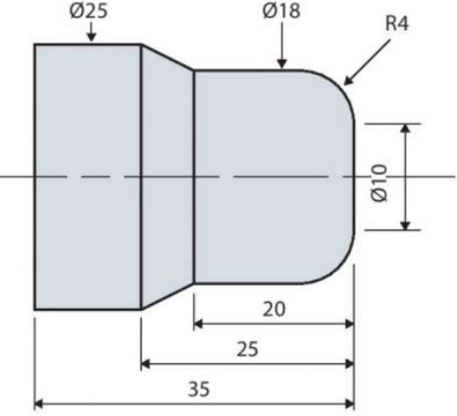
Creating the component profile
The CAD system uses coordinate positioning to build accurate profiles. Key steps include:
- Using grid snap for precise positioning
- Setting coordinate points for each feature
- Creating continuous paths to define the component outline
- Adding fillets and chamfers for realistic geometry
Programme generation and testing
Once the CAD drawing is complete, the CAM software converts it into machine code. Simulation allows the programme to be tested virtually, checking for errors before actual machining. This prevents machine damage and material waste.
Manufacturing process
The manufacturing cycle includes important setup procedures:
- Billet stick-out - Ensuring adequate material length extends from the chuck
- Tool positioning - Setting precise tool offsets and park positions
- Program verification - Double-checking through simulation before cutting
Only begin actual machining with proper instruction, permission and supervision.
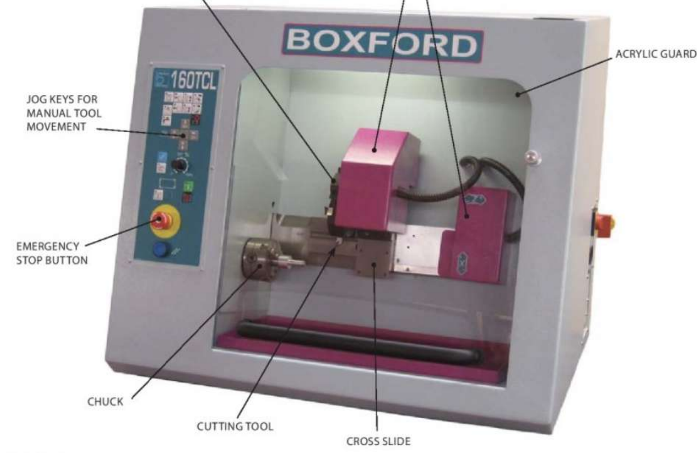
CNC laith tooling and operation
Tool types
Common CNC laith tools include:
- Left and right-hand turning tools (55° angles)
- Drill bits for creating holes
- Boring bars for enlarging existing holes
- Centre drills for starting holes accurately
- Parting tools for cutting components to length
- Threading tools for creating screw threads
Manual controls
Jog keys allow manual tool movement in X and Z directions for:
- Setting up workpieces
- Positioning tools
- Taking trial cuts
- Setting tool offsets
Manual mode enables operator control of all machine functions including chuck rotation speed and tool movement.
3D printing technology
3D printing represents another important CAD/CAM manufacturing method. Originally used for creating design models (rapid prototyping), the technology now produces finished parts through additive manufacturing.

Fused deposition modelling (FDM)
FDM is a popular 3D printing method that works by:
FDM Process Steps:
Step 1: Heating thermoplastic filament in an extrusion head Step 2: Depositing molten plastic layer by layer onto a build platform Step 3: Building components through controlled horizontal movements Step 4: Using stepper motors for precise positioning Step 5: Solidifying each layer before adding the next
Common materials include ABS plastic, PLA (polylactic acid), and nylon.
Advantages and disadvantages of 3D printing
Advantages:
- Creates complex internal geometries impossible with traditional machining
- Minimal material waste compared to subtractive processes
- Faster prototyping and reduced development costs
- Design flexibility and customisation
- Applications in medical device manufacturing
Disadvantages:
- Limited material selection
- High costs for industrial-quality machines
- Size restrictions based on machine capacity
Laser cutting systems
Laser cutters use focused light beams to cut precise shapes from various materials including metals, plastics, wood and fabrics. Metal-cutting versions are more expensive but offer greater versatility.
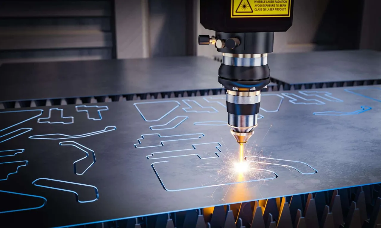
CAD software creates the component design, while CAM controls the laser head movement to cut the required shape.
Laser cutting advantages:
- Excellent accuracy and surface finish
- High-speed operation
- Handles complex shapes effectively
- Minimal material waste due to narrow cut width
- Reduced warping compared to other thermal processes
- Easy workpiece clamping
Key disadvantages:
- Expensive equipment costs
- Fume production requires effective extraction systems
- CAD knowledge necessary for programming
Desktop cutter plotters
These CAD/CAM systems primarily cut shapes from vinyl materials. The computer programme controls both the material positioning and blade movement along a track system.
Applications include:
- Decorative vinyl graphics for signage
- Masking materials for painting and etching
- Vinyl lettering and card making
- Magnetic sheet designs
- Heat transfer graphics for textiles
The blade can often be replaced with plotting pens for drawing applications.
Key Points to Remember:
-
CNC technology combines computer control with precision machining for consistent, accurate manufacturing
-
CAD creates the design while CAM generates the machine program - both are essential for modern manufacturing
-
Different manufacturing processes have unique advantages - CNC turning for cylindrical parts, 3D printing for complex geometries, laser cutting for flat materials
-
Simulation and testing prevent costly mistakes - always verify programmes before actual manufacturing
-
Safety and supervision are essential - CNC machines are powerful tools requiring proper training and oversight