Lathework (Junior Cert Engineering): Revision Notes
Lathework
What is a centre laith?
A centre laith is one of the most essential machine tools used in engineering and manufacturing. This versatile machine is primarily designed for turning operations, where material is removed from a rotating workpiece using a stationary cutting tool. The laith enables engineers and machinists to create cylindrical shapes, face surfaces, drill holes, and perform many other precision machining operations.

The laith operates on a simple principle: the workpiece rotates whilst a cutting tool is fed into it to remove material. This fundamental concept allows for the creation of precise cylindrical components, from simple rods to complex threaded parts.
Main laith components
Understanding the main components of a centre laith is crucial for safe and effective operation. Each component has a specific function that contributes to the machine's overall capability.

Laith bed: This forms the foundation of the entire machine. Made from rigid cast iron, the bed provides a stable platform and includes precisely machined slideways on top. These slideways guide the carriage and tailstock as they move along the bed length. The headstock is permanently mounted at the left end, whilst some beds feature a gap near the headstock to accommodate larger diameter workpieces.
The laith bed is the foundation of all machining accuracy. Any wear or damage to the bed slideways will directly affect the precision of all work performed on the laith.
Headstock: This houses the main spindle and contains the gear systems that provide various spindle speeds. The spindle can accommodate different workholding devices such as chucks, face plates, or driving plates. The spindle is hollow, allowing long bars to pass through, and features a Morse taper at the nose end for mounting laith centres.
Tailstock: Positioned at the right end of the bed, the tailstock can slide along the slideways and be locked in any position. Its barrel contains a Morse taper to hold laith centres, supporting the outer end of long workpieces. The tailstock can also hold drill chucks and various drilling tools for hole-making operations.
Carriage system: This consists of the saddle (which spans across the laith bed) and the apron (which hangs down at the front). The carriage moves along the bed between the headstock and tailstock, carrying the cutting tools to perform machining operations.
Cross slide: Mounted on the saddle, this component moves the cutting tool at right angles to the laith bed, enabling facing operations and controlling the depth of cut during turning.
Top slide (compound slide): Fitted on top of the cross slide, this carries the toolpost and cutting tool. It can be rotated to any required angle, making it essential for turning tapers and angled surfaces.
Workholding devices
Secure workholding is fundamental to safe and accurate laith work. Different workholding methods are used depending on the workpiece shape, size, and the operations to be performed.
Chuck types
Three-jaw self-centring chuck: This is the most commonly used chuck for round and hexagonal workpieces. The three jaws are connected by a scroll mechanism, meaning they all move simultaneously when operated with a chuck key. This automatic centring provides reasonable accuracy for most work. The chuck typically comes with two sets of jaws - one for gripping small diameter work and another for large diameter pieces. Numbers are stamped beside each jaw slot to ensure proper reassembly.
Four-jaw independent chuck: Each jaw can be adjusted independently using its own screw, making this chuck more versatile than the three-jaw version. It can hold square, round, rectangular, and irregularly shaped workpieces. Whilst it takes longer to set up, it provides greater accuracy than the self-centring chuck. The concentric circles on the chuck face serve as guides when positioning the workpiece.
Chuck Selection Guide:
- Use three-jaw chucks for speed and convenience with round or hexagonal stock
- Use four-jaw chucks when maximum accuracy is required or for irregular shapes
- Always ensure jaws are properly tightened and check workpiece security before starting
Laith centres
Laith centres provide support for long workpieces that might otherwise deflect or vibrate during machining. They feature Morse tapered shanks and are typically finished to a 60-degree included angle.
Live centres: These rotate with the workpiece and are mounted in the headstock. Since there's no relative motion between the centre and workpiece, they don't require hardening but should be kept well-lubricated.
Dead centres: These are stationary and mount in the tailstock. They must be hardened to resist wear as the workpiece rotates against them. Proper lubrication is essential to prevent seizure and maintain accuracy.
Rotating centres: Sometimes used in the tailstock, these feature bearings that allow rotation with the workpiece, combining the benefits of both live and dead centres.
Toolposts and tool holders
The toolpost system holds and positions cutting tools accurately. Different toolpost designs offer various advantages depending on the type of work being performed.

American type toolpost: Features a tool holder that rests on a segmented rocker. When the locking screw is loosened, the tool holder can be rocked to achieve the correct height. One screw secures both the tool holder and toolpost in position. This system allows easy height adjustment but isn't suitable for heavy cutting operations, and the tool angles change as the tool is rocked.
Four-way toolpost: Can hold four different tool holders simultaneously. The required tool is brought into position by releasing the locking lever and rotating the toolpost. This design is excellent for jobs requiring multiple different tools, allowing quick tool changes without individual setup.
Quick change toolpost: Consists of two parts - one remains on the top slide whilst the other (tool holder clamp) can be quickly removed. Tools can be changed rapidly, and once the height is set, the tool returns to the same position each time it's refitted. However, each tool requires its own separate holder.
Toolpost Selection Tips:
- American type: Best for simple operations requiring occasional height adjustment
- Four-way type: Ideal for production work with multiple tool requirements
- Quick change type: Most efficient for frequent tool changes in varied operations
Tool holder types
Tool bit holders: Available in right-hand, left-hand, and straight configurations, these holders accept high speed steel bits that can be reground when worn. They offer fine height adjustment by moving the tool bit in or out of the holder. However, multiple holders may be needed for different operations, and tool bits must be reset to centre height after each regrinding.
Insert tool holders: Designed for carbide inserts, these allow quick tool changes and can accommodate smaller inserts for cost savings. Different holders are required for different insert shapes and operations, but the ability to quickly replace worn inserts makes them very efficient for production work.
Laith cutting tools
The choice of cutting tool significantly affects machining performance, surface finish, and productivity. Two main types of cutting tools are commonly used on lathes.

High speed steel (HSS) bits
HSS tool bits offer several advantages that make them popular for general machining:
- Regrindability: When the cutting edge becomes dull, HSS bits can be reground to restore sharpness and even reshape for specific operations
- Heat resistance: They maintain hardness at high temperatures and cutting speeds
- Versatility: Can be ground to virtually any required shape
However, HSS tools require more setup time for grinding and adjustment. Excessive tool overhang can lead to chatter and vibration, and they need regular resharpening to maintain performance.
Carbide inserts
Carbide inserts represent modern cutting tool technology and offer distinct advantages:
- Superior heat resistance: Can withstand higher temperatures and cutting speeds than HSS
- Excellent wear resistance: Maintain sharp cutting edges longer than HSS tools
- Multiple cutting edges: Most inserts have several cutting edges, maximising tool life
The main disadvantages include difficulty in resharpening with standard grinding equipment and the need for different insert shapes for different operations, which can increase tooling costs.
Tool Selection Guidelines:
- Choose HSS bits for versatility, small batch work, and when custom tool shapes are needed
- Choose carbide inserts for production work, harder materials, and when maximum tool life is important
- Never mix tool types in the same operation without adjusting speeds and feeds accordingly
Tool angles and geometry
Proper tool geometry is essential for effective cutting action and good surface finish. The key angles that affect performance are clearance and rake angles.
Clearance angles: These ensure that only the cutting edge contacts the workpiece. Insufficient clearance weakens the tool and causes chattering, whilst excessive clearance also weakens the tool structure.
Rake angles: These facilitate chip removal during cutting. Excessive rake weakens the tool and may cause chatter, particularly important for hard, brittle materials which typically require smaller rake angles, whilst soft, ductile materials can use larger rake angles.
Tool height effects
The position of the cutting tool relative to the workpiece centre significantly affects the rake and clearance angles:
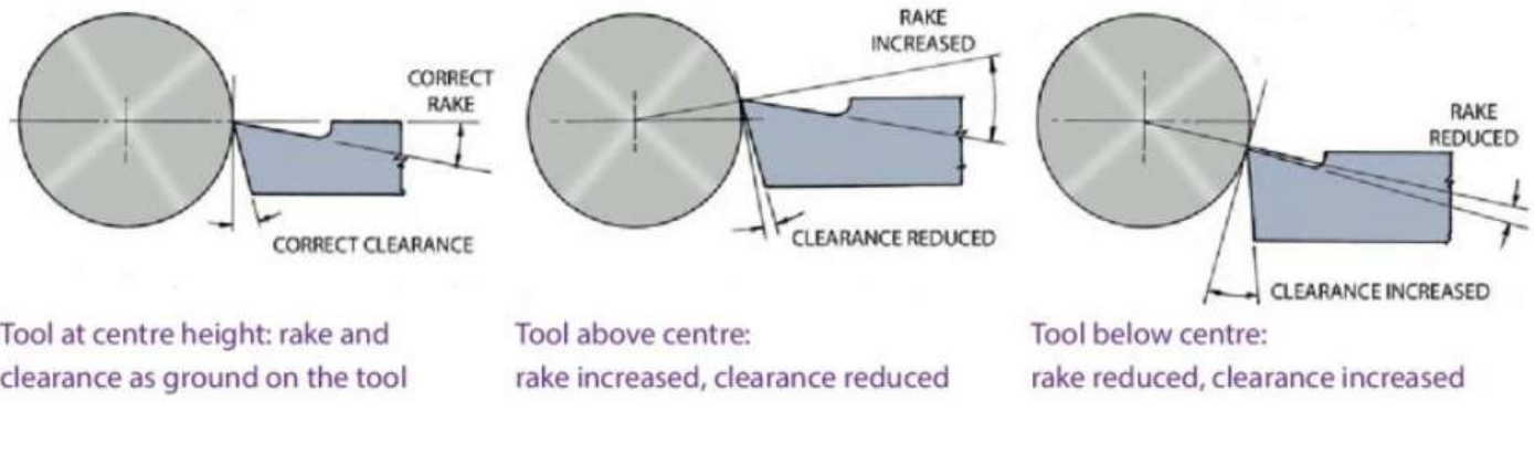
Tool at centre height: Provides the rake and clearance angles as ground on the tool - this is the ideal position for most operations.
Tool above centre: Increases the effective rake angle but reduces clearance, which can lead to rubbing and poor surface finish.
Tool below centre: Reduces the effective rake angle but increases clearance, which can cause increased cutting forces and possible chatter.
Critical Tool Positioning: For facing operations, it's particularly important to have the tool at centre height to ensure the faced surface is truly flat and perpendicular to the axis. Incorrect tool height is one of the most common causes of poor surface finish and premature tool wear.
Turning operations
The laith can perform a wide variety of machining operations, each serving specific purposes in component manufacture.
Basic operations
Facing: The cutting tool moves at right angles to the axis of rotation to machine the end surface of the workpiece. This operation creates a flat, square end and removes material waste. The cross slide is used to feed the tool from the outside diameter towards the centre.
Parallel turning: The tool moves parallel to the workpiece axis, creating a cylindrical shape and reducing the diameter. This is the most common laith operation, used to create shafts, rods, and cylindrical features.
Advanced operations
Taper turning: The tool moves at an angle to the workpiece axis to create tapered surfaces. For accurate tapers, the top slide should be set to half the included angle of the required taper.
Worked Example: Setting Up for Taper Turning
To turn a 1:10 taper (where the diameter reduces by 1mm for every 10mm of length):
Step 1: Calculate the included angle
- Taper angle = arctan(1/20) = 2.86°
Step 2: Set the top slide
- Set top slide to half the included angle = 1.43°
Step 3: Use top slide feed for the taper cut
Centre drilling: Uses a centre drill held in the tailstock to create starting holes for subsequent drilling operations or to accommodate laith centres. The centre drill creates both a pilot hole and a countersink in one operation.
Drilling: The drill is fed into the rotating workpiece. Parallel shank drills are held in a drill chuck mounted in the tailstock, whilst taper shank drills can be held directly in the tailstock barrel, sometimes with a sleeve for proper fit.
Knurling: Creates a diamond or straight pattern on the workpiece surface for improved grip. The workpiece rotates slowly whilst hardened wheels are pressed into the surface, displacing material to create the textured pattern.
Parting off: A narrow tool cuts completely through the workpiece to separate the finished part from the remaining stock. This operation requires careful technique to prevent tool breakage and should be performed close to the chuck for maximum rigidity.
Undercutting: A narrow tool creates grooves in the workpiece, often to allow components to fit closely together at shoulders or to provide clearance for threading operations.
Operation Tips:
- Always ensure adequate workpiece support for long pieces during turning operations
- Use proper cutting speeds and feeds for each material and operation type
- Keep cutting tools sharp and properly positioned for best results and safety
Cutting speeds and calculations
Proper cutting speeds are essential for efficient machining, good surface finish, and maximum tool life. Laith spindle speeds are measured in revolutions per minute (RPM), whilst cutting speeds for tools are given in metres per minute.
The cutting speed refers to the surface speed of the workpiece. For the same cutting speed, smaller diameter work requires higher rotational speeds than larger diameter pieces.
Speed calculation formula
To calculate the appropriate laith speed, use this formula:
Where:
- = rotational speed in rev/min (RPM)
- = cutting speed in metres/min
- = diameter of workpiece in mm
- = 3.14 (approximately 3 is sufficiently accurate for these calculations)
Worked Example: Speed Calculation
To turn a 25mm diameter mild steel bar at a cutting speed of 30m/min:
Step 1: Identify the known values
- = 30 m/min
- = 25 mm
- ≈ 3
Step 2: Apply the formula RPM
Therefore, set the laith to approximately 400 RPM.
Factors affecting cutting speeds
Several factors must be considered when selecting appropriate cutting speeds:
- Material type: Hard, tough materials require lower speeds than soft, ductile ones
- Tool type: Carbide-tipped tools can operate at higher speeds than high speed steel tools
- Operation type: Light finishing cuts can use higher speeds than heavy roughing cuts
- Coolant use: Coolants allow higher cutting speeds by reducing heat buildup
- Workholding method: Some workholding methods provide better support, allowing higher speeds
Safety guidelines
Safe laith operation is paramount for preventing accidents and injuries. Always follow these essential safety guidelines:
Critical Safety Requirements:
- Never operate the laith without proper instruction and demonstrated competence
- Avoid loose clothing that could catch in rotating parts
- Always wear appropriate protective equipment, particularly safety goggles
Before Starting the Laith:
- Ensure both workpiece and cutting tools are securely fastened
- Check that rotating parts can move freely without striking anything
- Never leave the chuck key in the chuck - remove it immediately after use
- Keep cutting tools clear of the workpiece when starting the laith
During Operation:
- Stop the laith completely before checking work or making measurements
- Never attempt to handle swarf (metal chips) whilst the machine is running
- Maintain a clean, tidy work area but ensure the laith is switched off before cleaning
Remember!
Key Points to Remember:
-
The laith is a versatile turning machine with key components including headstock, tailstock, carriage, and cross slide that work together to perform precision machining operations.
-
Choose the right workholding method - three-jaw chucks for round work requiring speed, four-jaw chucks for irregular shapes requiring accuracy, and laith centres for long workpieces needing support.
-
Tool selection matters - HSS bits can be reground and reshaped but carbide inserts offer superior performance at higher speeds and longer tool life.
-
Proper tool positioning is critical - tools must be set at centre height for optimal cutting angles, and different operations require specific tool movements and setups.
-
Calculate speeds correctly using the formula and consider material type, tool type, and operation when selecting cutting speeds for efficient, safe machining.