Iron-Carbon Equilibrium Diagram (Leaving Cert Engineering): Revision Notes
Iron-Carbon Equilibrium Diagram
What is the iron-carbon equilibrium diagram
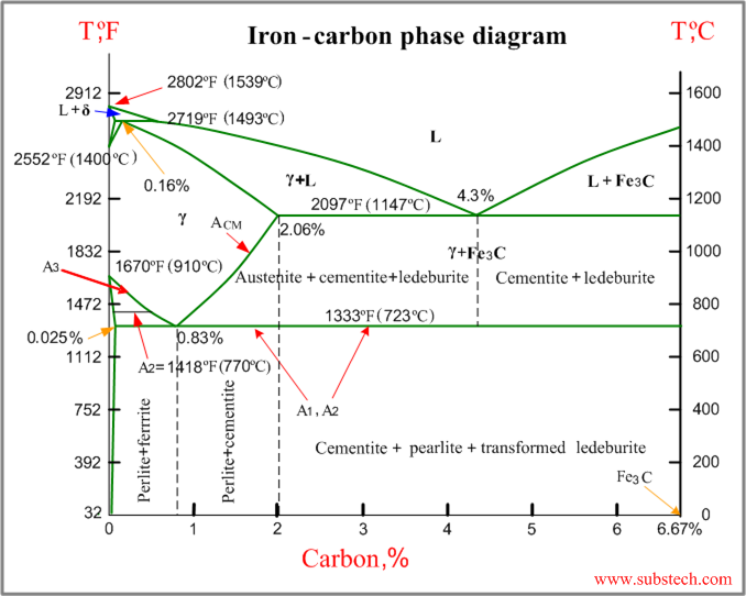
The iron-carbon equilibrium diagram is a graphical representation that shows the relationship between temperature and carbon content in iron-carbon alloys. This diagram helps engineers understand how the structure of steel changes under different conditions.
This diagram is fundamental to metallurgy and steel production, serving as the foundation for understanding how steel properties can be controlled through composition and heat treatment.
The diagram displays:
- Temperature on the vertical axis (measured in °C, ranging from 0-1000°C)
- Carbon content on the horizontal axis (measured as percentage, ranging from 0-1.8%)
- Five distinct regions numbered 1-5, each representing different phase combinations
Key phases in iron-carbon alloys
Understanding the main phases that form in iron-carbon alloys is essential for interpreting the equilibrium diagram.
Austenite
Austenite is a solid solution where carbon atoms are dissolved within the iron structure. This phase has several important characteristics:
- Forms at high temperatures (above 910°C)
- Has a face-centred cubic (FCC) crystal structure
- Appears in regions 1, 2, and 3 of the diagram
- Acts as the starting point for most heat treatment processes
Austenite's FCC structure allows it to dissolve much more carbon than ferrite, making it crucial for understanding steel transformations during heating and cooling.
Ferrite
Ferrite is nearly pure iron with very low carbon content. Key features include:
- Has a body-centred cubic (BCC) crystal structure
- Exists at temperatures below 810°C
- Appears in regions 4 and 5 of the diagram
- Provides ductility and toughness to steel
Pearlite
Pearlite is a mixture consisting of alternating thin layers of ferrite and cementite. This phase:
- Forms during slow cooling processes
- Creates a relatively soft material
- Appears in regions 4 and 5 alongside ferrite
- Results from the transformation of austenite below 723°C
Cementite
Cementite is an iron carbide compound that:
- Contains high carbon content
- Provides hardness to the steel
- Forms thin layers within pearlite
- Appears in regions 3 and 5 of the diagram
Critical temperatures
Two critical temperatures play crucial roles in steel heat treatment:
Lower critical temperature (723°C)
- Marks the boundary where austenite begins to transform
- Below this temperature, pearlite and ferrite start to form
- Essential for understanding normalising and annealing processes
Upper critical temperature (910°C)
- Above this temperature, the steel structure becomes fully austenitic
- The FCC crystal structure dominates at these temperatures
- Important for hardening heat treatments
These critical temperatures are fundamental reference points for all steel heat treatment processes. Understanding their significance is essential for controlling steel properties.
Cooling processes and structural changes
The rate at which steel cools from high temperatures dramatically affects its final properties and structure.
Slow cooling from 900°C
When 0.4% carbon steel cools slowly from 900°C, the following transformation occurs:
Worked Example: Slow Cooling Transformation
Step 1: Starting condition At 900°C, the steel exists as austenite with carbon dissolved in the FCC structure
Step 2: Cooling process As temperature drops below 723°C, the austenite gradually transforms
Step 3: Final structure Ferrite and soft pearlite form, creating the softest possible material
Step 4: Crystal change The structure changes from FCC (austenite) to BCC (ferrite) below 810°C
This slow cooling process allows carbon atoms sufficient time to move and form the equilibrium phases shown in the diagram.
Rapid cooling (quenching) from 900°C
When the same steel undergoes rapid cooling (quenching) from 900°C, a completely different transformation takes place:
Worked Example: Rapid Cooling (Quenching) Transformation
Step 1: Starting condition Steel begins as austenite at 900°C
Step 2: Rapid cooling The quick temperature drop prevents normal phase transformations
Step 3: Final structure Martensite forms instead of the equilibrium phases
Step 4: Characteristics Martensite has a hard, needle-like structure that creates a strong but brittle material
Step 5: Cause The rapid cooling traps excess carbon in the structure, preventing it from forming separate phases
Martensite formation is not shown on the equilibrium diagram because it represents a non-equilibrium condition. This is why quenching creates properties different from those predicted by the equilibrium diagram.
Regions of the equilibrium diagram
The five numbered regions on the diagram represent different phase combinations:
- Region 1: Austenite only
- Region 2: Austenite phase
- Region 3: Austenite and cementite
- Region 4: Pearlite and ferrite
- Region 5: Pearlite and cementite
Each region indicates which phases will be present at specific temperature and carbon content combinations.
By locating any point on the diagram using temperature and carbon content coordinates, engineers can predict exactly which phases will be present in the steel under equilibrium conditions.
Practical applications
Understanding the iron-carbon equilibrium diagram enables engineers to:
- Predict steel properties based on carbon content and temperature
- Design appropriate heat treatment cycles
- Select suitable cooling rates for desired material properties
- Control the balance between hardness and ductility in steel components
Key Points to Remember:
- Austenite forms at high temperatures with an FCC crystal structure and acts as the foundation for heat treatment
- Critical temperatures of 723°C and 910°C mark important transformation points in steel
- Slow cooling produces soft pearlite and ferrite, while rapid quenching creates hard, brittle martensite
- The equilibrium diagram maps five distinct regions showing different phase combinations based on temperature and carbon content
- Crystal structures change from FCC (austenite) at high temperatures to BCC (ferrite) at lower temperatures