Introduction to Welding (Leaving Cert Engineering): Revision Notes
Introduction to Welding
What is welding?
Welding is a fundamental manufacturing process used to permanently join metals together. It works by melting the base materials at their meeting point and allowing them to fuse together, creating a strong bond when cooled. This process can be performed with or without additional filler metal to strengthen the joint.
Welding occurs at the molecular level, where the metals actually become one continuous piece rather than just being stuck together. This creates a much stronger bond than mechanical fastening methods like bolts or screws.
The process involves heating metals to their melting point using various heat sources, then allowing them to cool and solidify into a single, unified structure.
Modern welding includes several common processes:
- Gas Metal Arc Welding (GMAW) - also known as MIG welding
- Gas Tungsten Arc Welding (GTAW) - also known as TIG welding
- Flux Core Arc Welding
- Stick Welding
Each process has specific applications and is chosen based on the materials being joined, the required strength, and the working environment.
Essential welding terminology
Understanding welding terminology is crucial for anyone learning the craft. These terms form the foundation of welding knowledge and appear frequently in technical drawings and specifications.
Basic welding terms
Arc burn - A metallurgical defect that occurs when the welding arc accidentally strikes the base metal outside the intended weld area. This creates a small notch or mark that can weaken the material and should be avoided through proper technique.
Arc burns are serious defects that can significantly weaken the base metal. Always maintain proper arc control and avoid striking the arc outside the intended weld area.
Base metal - The original metal pieces that you want to join together. This is also commonly referred to as the workpiece. The base metal provides the foundation for the weld and determines many of the welding parameters you'll use.
Weld metal - The molten metal that forms during the welding process. This includes both melted base metal and any filler metal that's added. Once cooled, this becomes the actual weld that holds the pieces together.
Heat-affected zone (HAZ) - The area of base metal immediately surrounding the weld that gets hot enough to change its properties but doesn't actually melt. This zone can become harder or softer than the original metal, affecting the overall strength of the joint.
The heat-affected zone is often overlooked but plays a critical role in weld quality. Understanding how heat affects the surrounding metal helps predict joint performance and potential failure points.
Welding process terms
Weld pass - A single progression of welding along the joint line. Complex welds often require multiple passes to build up the proper thickness and ensure complete penetration.
Cover pass - The final weld pass that creates the finished surface of the joint. This pass sits higher than the surrounding metal and often overlaps the previous passes for a smooth, strong finish.
Hot pass - A welding pass that follows immediately after the initial stringer pass (the first pass). The hot pass helps ensure good penetration and removes any defects from the root pass.
Electrical terms
Polarity - Describes how the electrode and workpiece connect to the power supply in arc welding. There are two types:
- DCEN (Direct Current Electrode Negative) - also called straight polarity
- DCEP (Direct Current Electrode Positive) - also called reverse polarity
The choice of polarity affects heat distribution, penetration depth, and the overall quality of the weld.
Welding electrode - In arc welding, this conducts electrical current to create the arc that melts the metals. The electrode may also provide filler metal as it melts during the process.
Specialised welding processes
Spot welding - A process where two metal pieces are pressed together and current is passed through a small spot to melt and fuse them at that location. This technique works well for thin metals (0.5 to 3 mm thick).
Plug welding - Involves filling a hole in one piece with weld metal to attach it to the surface of another piece underneath.
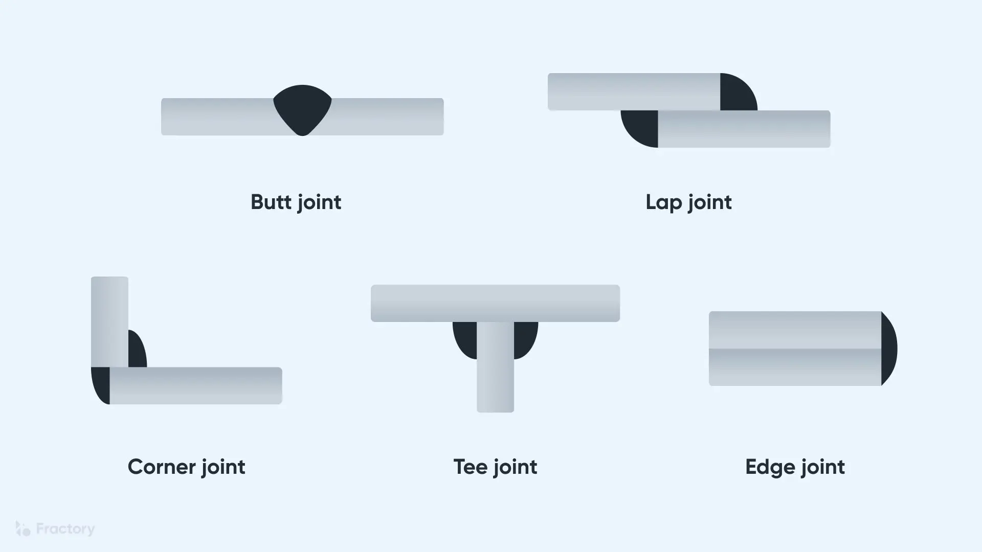
Types of weld joints
There are five standard types of weld joints used throughout the welding industry. Each joint type has specific applications and strength characteristics that make it suitable for different situations.
The joint type you choose significantly affects the strength, appearance, and cost of your welded assembly. Understanding when to use each type is essential for successful welding projects.
Corner joint
A corner joint forms when two pieces of metal meet at their edges in a perpendicular arrangement, creating an L-shape or corner configuration. One piece's edge meets the end face of the other piece.
Corner joints are commonly used in:
- Box construction
- Frame assemblies
- Sheet metal work
There are several variations including full corner welds and half-overlap designs, each offering different benefits for specific applications.
Edge joint
An edge joint connects two pieces of metal along their edges when they're positioned in parallel planes. The weld bead runs along the joined edges but doesn't penetrate completely through the joint thickness.
Edge joints have significant limitations and should not be used in high-stress applications or pressure vessels. They are only suitable for light structural loads and sealing applications.
This joint type works well for sealing applications and light structural work where maximum strength isn't required.
Lap joint
A lap joint occurs when one piece of metal overlaps another, and a weld bead is created on the surface where they meet. For best results, lap joints should be performed with no gap between the two pieces.
Key characteristics of lap joints:
- Easy to set up and weld
- Good for joining different thicknesses
- Creates strong shear resistance
- Commonly used in repair work
Tee joint
A tee joint forms when the edge of one workpiece meets the surface of another workpiece at a right angle, with material present on both sides of the connecting edge. This creates a T-shaped configuration.
Tee joints are frequently used in:
- Structural steelwork
- Pipe connections
- Support brackets
- Framework construction
Butt joint
Butt joints are created when two workpieces are aligned on the same plane and joined along their edges with a weld. This joint type is preferred for high-strength applications because it distributes stress more effectively than other weld types.
Butt joints are considered the strongest joint type when properly executed because they create continuous stress flow through the connection without the stress concentrations found in other joint designs.
Advantages of butt joints:
- Maximum strength potential
- Even stress distribution
- Clean appearance when finished
- Suitable for pressure applications
Butt joints require precise preparation and alignment but provide the strongest possible connection when properly executed.
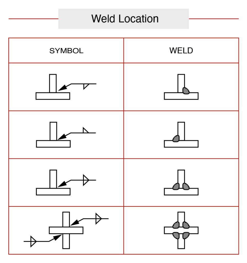
Welding symbols
Welding symbols provide a standardised way to communicate welding requirements on technical drawings. Understanding these symbols is essential for interpreting blueprints and ensuring welds meet specifications.
Basic symbol components
Reference line - The horizontal line that serves as the foundation of every welding symbol. This line designates the type of weld, its location, size, extent, contour, and many other pieces of vital information.
Arrow - Points to the specific joint or area where welding is required. The arrow connects the reference line to the actual work location.
Arrow side and other side - Welding symbols have two sides: the arrow side (where the arrow points) and the other side (opposite the arrow). This distinction helps specify exactly where the weld should be placed relative to the joint.
Supplementary symbols
Weld-all-around symbol - A circle placed at the junction of the reference line and arrow indicates that the weld should continue completely around the entire joint.
Field weld symbol - A triangular flag symbol indicates that the welding will be performed in the field (on-site) rather than in the workshop.
Weld symbols vs welding symbols
It's crucial to distinguish between weld symbols (which indicate the desired type of weld like fillet or groove) and welding symbols (the complete notation including reference line, arrow, and all specifications).
Dimensions and specifications
Welding symbols include numerical information about:
- Weld size (leg length for fillet welds)
- Length of weld required
- Spacing for intermittent welds
- Penetration depth requirements
Finish symbols
Finish symbols specify how the weld should be shaped or ground after completion. These symbols indicate whether the weld needs grinding, machining, or other finishing operations to meet requirements.
Tail information
The tail of a welding symbol contains additional information about:
- Welding process to be used
- Specific welding procedures
- Material specifications
- Quality requirements
When no special information is needed, the tail may be omitted from the symbol. However, when present, the tail contains critical information that affects how the weld should be performed.
Remember!
Key Points to Remember:
-
Welding joins metals permanently by melting and fusing them together at the molecular level, creating a continuous bond stronger than mechanical fastening methods.
-
Master the five joint types - corner, edge, lap, tee, and butt joints each have specific applications, with butt joints providing maximum strength for critical applications.
-
Welding symbols are a universal language - learning to read the reference line, arrow, and supplementary symbols allows you to interpret welding requirements on any technical drawing.
-
Terminology matters - understanding terms like base metal, heat-affected zone, and polarity is essential for discussing welding processes and troubleshooting problems.
-
Safety and quality go together - proper technique prevents defects like arc burn while ensuring strong, reliable welds that meet engineering specifications.