Scale Drawing, Plans, and Elevations (HSC SSCE Mathematics Standard): Revision Notes
Scale Drawing, Plans, and Elevations
Introduction to scale drawings
Scale drawings are essential tools that allow us to represent real objects at a smaller, more manageable size while maintaining accurate proportions. These drawings are used extensively in many fields including architecture, engineering, and cartography. The key principle behind scale drawings is that all measurements are reduced or enlarged by the same factor, which means the drawing maintains the same proportions as the actual object.
The scale factor is the ratio that compares the size of the drawing to the actual size of the object. For example, maps are scale drawings that represent large geographical areas on paper. A map of Australia might be only a few centimetres across, but it accurately represents a continent that spans thousands of kilometres.

Scale drawings are everywhere in our daily lives! Beyond maps, you'll find them in furniture assembly instructions, model kits, technical manuals, and even smartphone screen displays. Understanding scale drawings is a practical skill that extends far beyond the mathematics classroom.
The measurements on a scale drawing have been systematically reduced to make the representation convenient to use and transport. Understanding how to work with scale drawings means being able to convert between the drawing measurements and actual real-world dimensions.
Understanding scale and scale notation
The scale of a drawing establishes the mathematical relationship between the drawing and reality. This relationship is expressed as a ratio in the following formula:
There are two standard ways to express scale, and it is important to understand both methods:
Method 1: Using units
This method explicitly states the units for both the drawing and the actual object. For example:
- (or written as )
- This tells us that every centimetre on the drawing represents metre in reality
Method 2: Using ratios without units
This method expresses the scale as a pure ratio. For example:
- This tells us that the actual distance is times the length shown on the scale drawing
- Both measurements must be in the same units when using this notation
When working with ratio notation, the number after the colon tells you the multiplication factor. A scale of means every unit on the drawing equals units in reality.
Critical reminder: When using ratio notation (like ), both the drawing measurement and actual measurement must be expressed in the same units before you can apply the scale factor!
Converting between drawing and actual measurements
To solve problems involving scale drawings, you need to convert between drawing measurements and actual measurements. The method depends on what information you have and what you need to find.
Finding actual length from drawing length:
- Multiply the drawing measurement by the scale factor
- Remember to convert units if necessary
Finding drawing length from actual length:
- Divide the actual measurement by the scale factor
- Remember to convert units if necessary
Worked Example: Using a Scale
Question: A scale drawing has a scale of .
a) Find the actual length if the drawing length is mm. Answer to the nearest centimetre.
b) Find the drawing length if the actual length is m. Answer to the nearest millimetre.
Solution for part a:
To find the actual length, multiply the drawing length by the scale factor.
Drawing length mm
Scale factor
Actual length mm
Convert millimetres to centimetres by dividing by :
Answer: 150 cm
Solution for part b:
To find the drawing length, divide the actual length by the scale factor.
Actual length m
Scale factor
Drawing length m
Convert metres to millimetres by multiplying by :
Answer: 90 mm
Exam tip: Always check your units carefully. In scale problems, you often need to convert between millimetres, centimetres, and metres. Write down your conversion steps clearly to avoid errors.
Plans and elevations
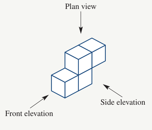
When representing three-dimensional objects in two dimensions, we use different views to show the complete structure. Plans and elevations are standard views used in technical drawing and architecture to communicate spatial information clearly.
Plan view is the view of an object when looking directly down from above. Imagine you are hovering over an object looking straight down at it. This top-down perspective is particularly useful for showing the layout and arrangement of spaces. In a house plan, you can see the arrangement of rooms, the positions of doors and windows, and the flow between spaces.
Elevation view is the view of an object when looking at it from one side. The most common elevation views are:
- Front elevation: the view when looking at the object from the front
- Side elevation: the view when looking at the object from the side
Unlike plans, which are horizontal sections, elevations are vertical sections that show the height and profile of objects. In house elevations, you can see the roof shape, window positions at different heights, and the overall external appearance of the building.
Memory tip: Think of Plan = Pan view - you're looking down into a pan from above. Think of Elevation = Eye level view - you're looking at the object from the side at eye level.
In architectural practice, plans and elevations work together to provide a complete picture. The plan shows you "what goes where" while elevations show you "what it looks like from outside."
Worked Example: Drawing Plan and Elevation Views
Question: Draw the plan view, front elevation and side elevation of the object shown.
Solution:
For the plan view: Imagine looking straight down at the object from above. You will see the outline of all the blocks as they appear from the top. The plan shows the horizontal extent of the object.
For the front elevation: Look at the object from directly in front. You will see how the blocks stack vertically when viewed from this angle.
For the side elevation: Look at the object from the side. This shows a different vertical profile and helps complete the three-dimensional understanding of the object.
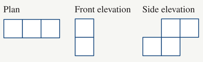
The three views together provide complete information about the object's three-dimensional structure. This orthographic projection method is used extensively in technical drawing and engineering.
Exam tip: When drawing plans and elevations, use a ruler and keep your lines straight. Make sure all three views align properly and represent the same object.
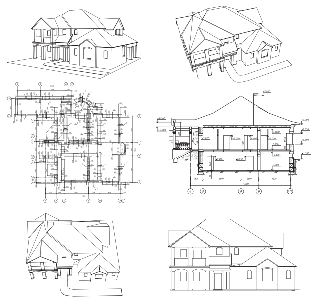
Building plans
Building plans are one of the most common and practical applications of scale drawings. Architects and builders use floor plans drawn to scale to communicate design ideas and construction specifications. These plans allow large buildings to be represented on manageable sheets of paper while maintaining accurate proportions.
Building plans typically use scale factors such as or . This means that every centimetre on the plan represents centimetres (or metres) in the actual building. By measuring distances on the plan and applying the scale factor, you can determine the actual dimensions of rooms, walls, and other features.
A floor plan is a horizontal section cut through a building at a certain height, showing:
- The arrangement and dimensions of rooms
- Wall positions and thicknesses
- Locations of doors and their opening directions
- Window positions
- Built-in fixtures and fittings
- Appliances and furniture (sometimes)
Common floor plan symbols
Understanding floor plan symbols is essential for reading building plans. These standardised symbols convey important information about the building's features:
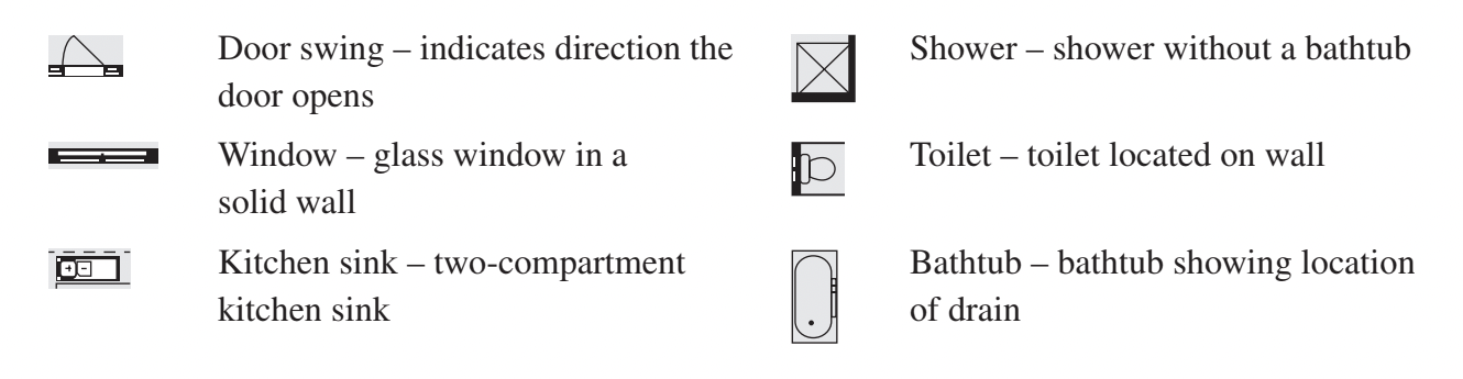
These symbols are standardised internationally, meaning architects and builders around the world can read and understand floor plans regardless of language barriers. Learning these symbols is like learning a universal visual language for buildings!
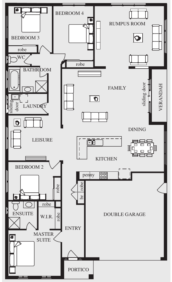
Worked Example: Finding Measurements from a House Plan
Question: A building plan is shown for the ground floor of a Metricon home with a scale of .
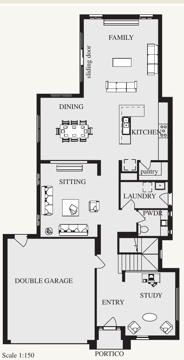
a) How many internal doors are there?
b) What is the meaning of PWDR?
c) What is the length of the house?
d) What are the dimensions of the double garage?
Solution:
Part a: Count the internal doors
Look for the door swing symbol on the floor plan. Internal doors are those that connect rooms inside the house, not external doors leading outside.
Answer: 4 internal doors
Part b: Meaning of PWDR
PWDR is a standard abbreviation used on building plans.
Answer: Powder room (a small bathroom with toilet and basin)
Part c: Length of the house
Step 1: Measure the length of the house on the floor plan using a ruler.
Drawing length cm
Step 2: The scale is , which means the actual length is times the drawing length.
Actual length cm
Step 3: Convert to metres: m
Answer: The length of the house is 18.9 m
Part d: Dimensions of the double garage
Step 1: Measure both dimensions of the garage on the floor plan using a ruler.
Drawing length cm
Drawing width cm
Step 2: Apply the scale factor to both measurements:
Actual length cm m
Actual width cm m
Answer: The dimensions of the double garage are 6.2 m × 5.3 m
Exam tip: When measuring from a floor plan, be as accurate as possible with your ruler. Small measurement errors get multiplied by the scale factor, so a mm error on a scale plan becomes a mm ( cm) error in the actual dimension. Always double-check your measurements.
Key Points to Remember:
- Scale drawings represent real objects at a different size while maintaining accurate proportions
- Scale can be expressed with units ( cm to m) or as a ratio ()
- To find actual length: multiply the drawing length by the scale factor
- To find drawing length: divide the actual length by the scale factor
- A plan is a top-down view of an object showing its layout
- An elevation is a side view of an object showing its height and profile
- Floor plans use standard symbols to represent doors, windows, fixtures and fittings
- Always check your units and convert when necessary (mm, cm, m)