Polarisation (HSC SSCE Physics): Revision Notes
Polarisation
What is polarisation?
Polarisation is a phenomenon that distinguishes waves from streams of particles. It relates specifically to the direction in which the electric field oscillates in electromagnetic radiation.
In the wave model of light, electromagnetic radiation consists of oscillating electric and magnetic fields that are perpendicular to each other. These fields propagate at right angles to both field directions at the speed of light. Polarisation refers to the particular direction of oscillation of the electric field in the transverse plane.
The direction of the oscillating electric field depends on how the charged particles that created the light were moving. For example, electrons oscillating vertically in a wire will produce vertically polarised electromagnetic radiation.
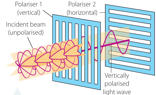
Light from incandescent sources (like light bulbs or the Sun) contains particles vibrating in all directions at different speeds, so this light is described as unpolarised.
Historical context
French physicist Etienne Louis Malus pioneered the study of polarisation through his investigations of light reflecting from polished surfaces. His work established polarisation as a key characteristic of the wave nature of light.
Plane polarisation
Plane polarisation means that all the electric fields in the electromagnetic radiation are oscillating in the same two-dimensional plane. When this occurs, the light waves all vibrate in one particular direction.
There are several ways to convert unpolarised light into plane-polarised light:
- Reflection from surfaces
- Scattering
- Passing through a polarising filter
Polarisation by reflection
When light from an incandescent source (such as the Sun) reflects off a flat surface like a lake, the charged particles at the surface respond to the incoming light. Water, even at pH 7, contains some H⁺ and OH⁻ ions, while seawater contains additional ions. These ions can oscillate parallel to the surface but not perpendicular to it.
Here's what happens:
- Incoming light with the wrong orientation is scattered or absorbed
- Light oriented parallel to the surface causes the ions to oscillate
- These oscillating ions emit electromagnetic radiation
- All this emitted radiation is polarised parallel to the surface
Therefore, reflected sunlight is plane-polarised. This polarisation can be detected using an analyser - a device that only allows light of a particular polarisation to pass through.
Malus' Law
The wave model allows us to understand the relationship between the intensity of polarised light and the angle at which it passes through an analyser.
Intensity and amplitude
The intensity () of the electric field in electromagnetic radiation is proportional to the square of its amplitude ():
Deriving Malus' Law
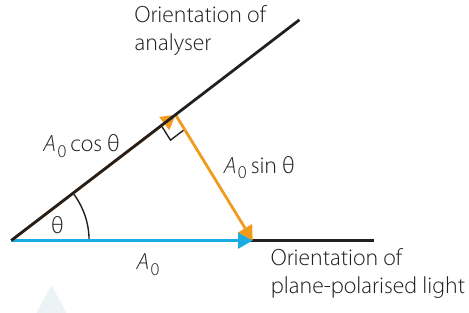
Consider plane-polarised light with electric field amplitude passing through an analyser oriented at angle to the polarisation direction. The electric field vector can be broken down into two components:
- Component parallel to the analyser:
- Component perpendicular to the analyser:
Worked Example: Deriving the Intensity Relationship
If the intensity of the incoming plane-polarised light is , then the intensity of light passing through the analyser will be:
Step 1: The transmitted amplitude is , so the intensity is proportional to its square:
Step 2: Taking the ratio of intensities:
Step 3: Rearranging gives us Malus' Law:
Since the maximum intensity occurs when (analyser parallel to polarisation), we can write:
This equation is known as Malus' Law. Note that .
Understanding Malus' Law
Malus' Law tells us:
- Minimum light (zero intensity) passes when the analyser is perpendicular to the polarisation plane ()
- Maximum light passes when the analyser is parallel to the polarisation plane ()
- Light intensity varies as the square of the cosine of the angle
Units of light intensity
The SI unit for light intensity is the lux. Light sources are often rated in lumen, which roughly represents the output of a candle. To account for distance and the inverse square law, we use the concept of flux - light output per unit area:
Investigation 10.5: Testing Malus' Law
Aim
To test the accuracy of Malus' Law
Materials
- Dissecting tray or other large, shallow, flat container
- Water
- Incandescent light source (desk lamp, light kit, or direct sunlight)
- Large sheet of cardboard (for shield)
- Scissors
- Plane polarising filter (analyser) - polarising plastic or sunglasses
- Stand/holder for analyser
- Diffraction grating mount
- Protractor
- Light meter or appropriate phone app
A horizontal polariser may be substituted for the flat tray of water.
Risk assessment
Safety Considerations:
| What are the risks? | How to stay safe |
|---|---|
| Sunlight can be blinding | Do not look directly at the Sun or its reflection |
| Desk lamps can cause temporary vision disturbance | Do not look directly at a desk lamp |
| Scissors can cause injury | Be careful when carrying or cutting with scissors |
Method
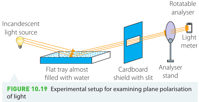
- Set up the tray and almost fill it with water
- Cut a slit in the cardboard shield and position it as shown in the diagram
- Place the light meter in position and record a background light reading
- Turn on the light source and record the light meter reading
- Position the analyser between the shield and light meter
- Record the light meter reading in a suitable table
- Rotate the analyser by 10°
- Repeat steps 6 and 7 until you have 18 readings
Results
Construct a table with the following columns:
- Relative orientation of analyser
- Measured light intensity
- Adjusted values (subtract background light from step 3)
- Angle relative to maximum intensity position
- Calculated values using Malus' Law
Processing Your Data:
The background reading represents unavoidable ambient light and should be subtracted from all other readings. The reading from step 4 represents .
Identify which reading had the analyser most nearly parallel to the plane polarisation direction - this sets .
Calculate expected values using Malus' Law:
Plot both your measured results (column 3) and calculated values (column 5) against the angle of rotation on the same graph.
Analysis of results
- Comment on the accuracy of your measurements and estimate the error
- Compare the plot of measured results with expected results
- Evaluate the reliability and validity of your results
- Identify any deficiencies and suggest improvements
Conclusion
Discuss whether the investigation met its aim. How well do your results agree with Malus' Law predictions? Since Malus' Law derives from the wave model of light, does your experimental evidence support this model?
Investigation 10.6: Monochromatic light and Malus' Law
Aim
To determine whether monochromatic light obeys Malus' Law
Additional materials
- Materials from Investigation 10.5
- Red, green, and blue filters
Method
- Place a red filter between the light source and polariser (water tray)
- Repeat steps 3-7 from Investigation 10.5
- Repeat for green and blue filters
Analysis
Compare results for different colours with those from Investigation 10.5. Examine whether:
- differs between individual colours
- Coloured filters significantly affect the relationship predicted by Malus' Law
- The wave model remains valid for monochromatic light
Remember!
Key Points to Remember:
-
Polarisation refers to the direction of oscillation of the electric field in electromagnetic radiation - it's a characteristic property of waves
-
Plane polarisation means all electric fields oscillate in the same two-dimensional plane
-
Unpolarised light can be polarised by reflection, scattering, or passing through a polarising filter
-
Malus' Law states that , where is the angle between the polarisation plane and the analyser orientation
-
Maximum light passes through an analyser when it's parallel to the polarisation plane; minimum (zero) light passes when perpendicular
-
The intensity of light is proportional to the square of its amplitude: