Minimising Power Transmission Losses (VCE SSCE Physics): Revision Notes
Minimising Power Transmission Losses
Introduction to power transmission
Electrical power in Australia is transmitted from power stations to homes and businesses using high-voltage transmission lines. Power stations are often hundreds of kilometres away from cities and towns, which means the resistance of the transmission wires cannot be ignored. When current flows through powerlines, electrical energy is lost as thermal energy due to the heating effect of the current. Minimising these losses is crucial for efficient power distribution.
Transmission line: A specialised powerline that carries electrical energy at high voltage between geographical locations, sometimes over very long distances.
Transmission loss: Electric power transformed to thermal energy, sound energy and kinetic energy as current passes through the resistance of the transmission wires. It is calculated from and sometimes expressed as a percentage of total power transmitted.
Why high-voltage AC transmission is used
The power loss problem
Although domestic consumers in Australia receive AC at for safety and convenience, power is generated at much higher voltages ( to ) and then stepped up even further for transmission. During peak demand in Victoria, up to of electrical power may be needed. The key question is: how can this power be transmitted efficiently with minimal losses?
The solution: step-up transformers
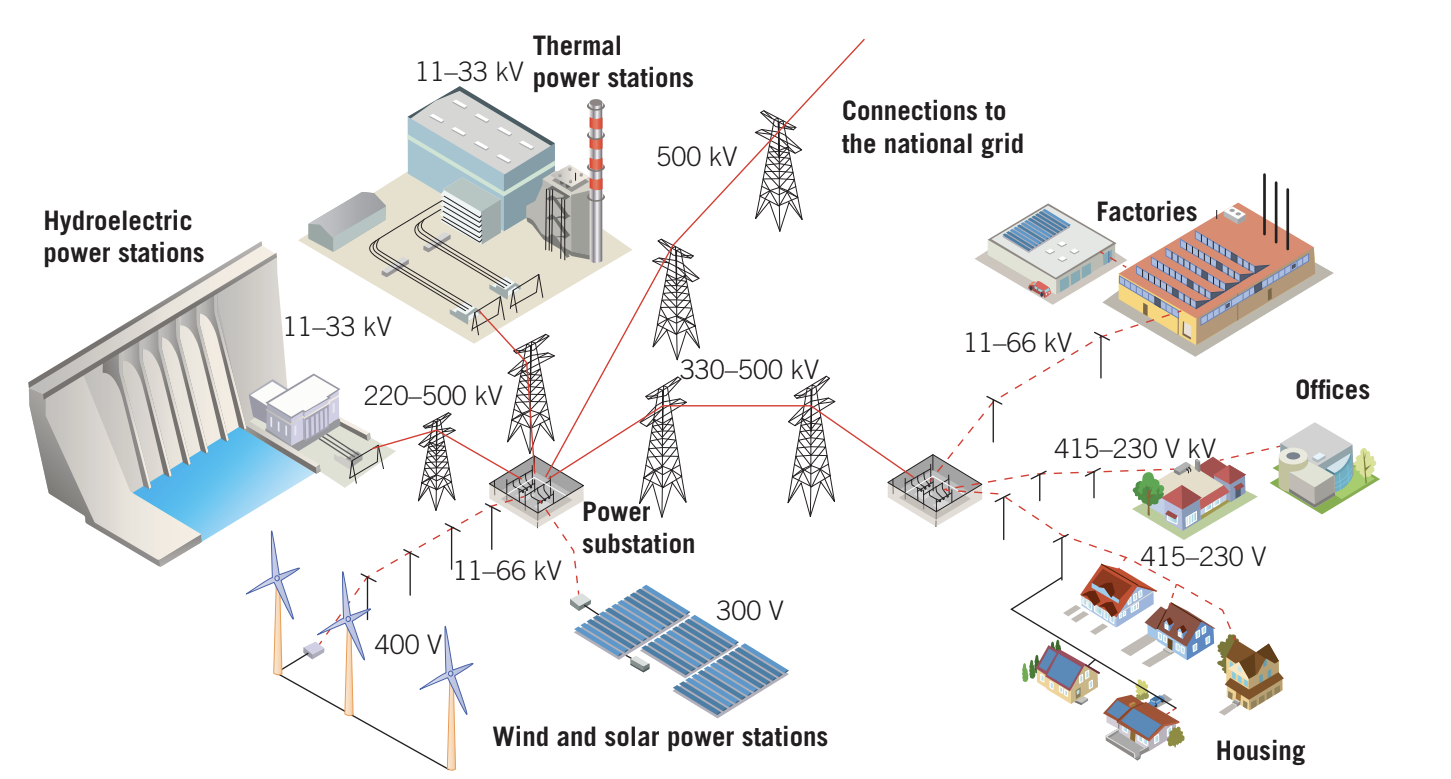
The answer lies in using step-up transformers to substantially increase transmission voltages as power leaves the power station. In Australia, voltages are typically stepped up to:
- (extra high voltage)
The voltage is then lowered using step-down transformers at substations near where the supply is required:
- or for factories, trains or trams
- or for smaller factories, schools and homes
The mathematics of power loss
Recall from Unit 1 these important relationships:
- Ohm's law:
- Power formulas:
The power loss in transmission lines is given by:
The Critical Insight About Power Loss
This formula reveals a crucial insight: power loss is proportional to the square of the current. This means:
- If voltage increases by a factor of 10, current decreases by a factor of 10
- Power loss decreases by a factor of 100 ()
Since the transmitted power must remain constant at any given moment, using higher voltage means lower current, which dramatically reduces transmission losses.
This is the main reason transformers are essential for power utilities, and why AC (which can be easily transformed) is preferred over DC for long-distance transmission.
The national grid and power distribution
Electricity distribution networks are constructed with two or more paths between major substations. If one path fails, electricity can be re-routed via an alternative path. The networks of the eastern and southern states, including Tasmania and the ACT, are connected to form the national grid.
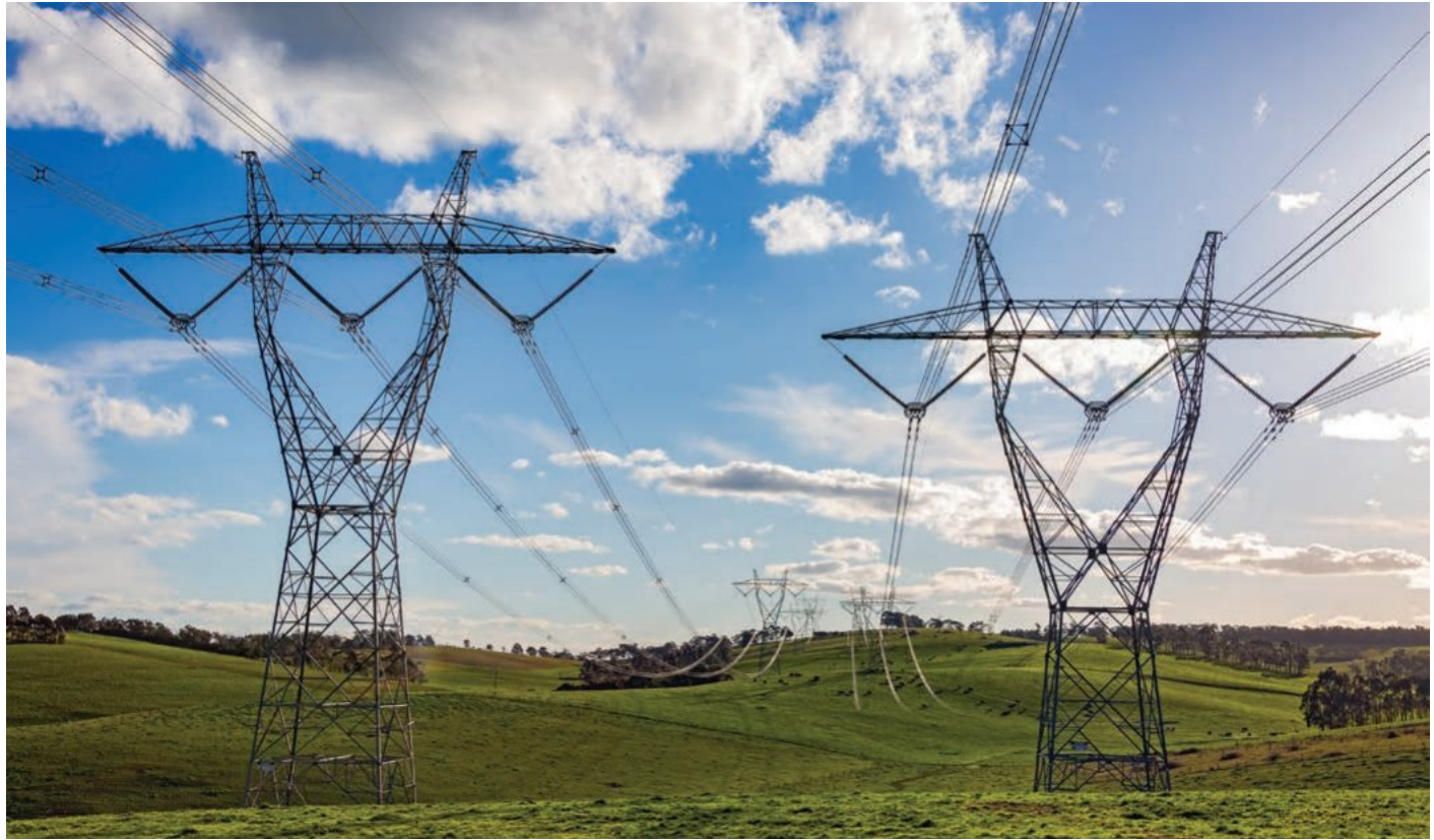
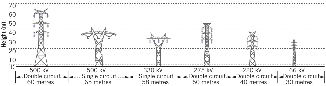
Powerlines consist of conducting cables supported by pylons with glass or porcelain insulators preventing earthing. Power is fed into the grid at different points from:
- Power stations (thermal, hydroelectric)
- Solar farms
- Wind farms
- Large-scale batteries
Worked examples: understanding power loss in transmission
Example 1: Power loss without transformers
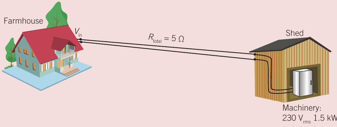
Consider a shed from a farmhouse. The electricity operates a , piece of machinery. The connecting wires have a total resistance of .
Worked Example: Calculating Power Loss Without Transformers
Part a: Calculate the power loss in the connecting wires
First, find the current through the machinery:
In a series circuit, this current is the same through the wires. The power lost in the wires:
This is over , more than 10% of the power for the machinery—a considerable waste!
Part b: Calculate the required input voltage at the house
The voltage at the house must be larger than to compensate for the voltage drop across the wires.
Voltage drop across wires:
Therefore:
Example 2: Power loss with a step-down transformer
Now suppose we install a step-down transformer at the shed, while the machinery still operates at , .
Worked Example: Dramatic Improvement with a Step-Down Transformer
Part a: Calculate the power loss with the transformer
From the turns ratio, the current in the wires is:
This is much smaller than without the transformer!
Power loss in wires:
The power loss is now about 1 W, compared to over 200 W without the transformer—a dramatic improvement!
Part b: Calculate the required input voltage
Voltage drop in wires:
Therefore:
Example 3: Comparing transmission at different voltages
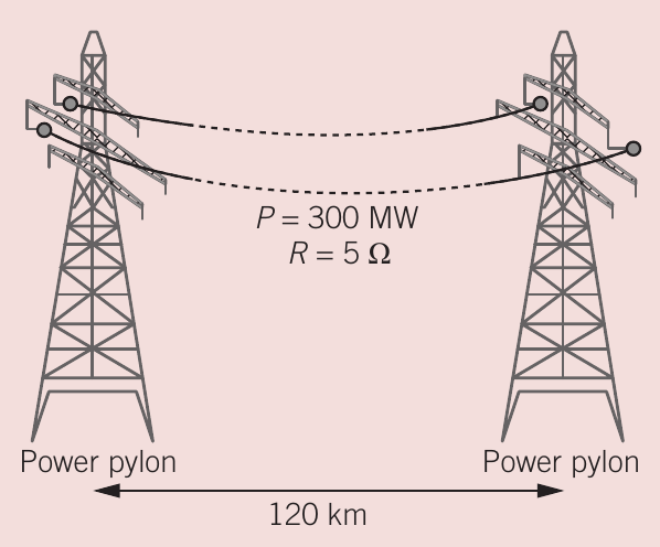
Consider transmitting over with transmission line resistance of . Compare transmission voltages of , , and .
Worked Example: Comparing Transmission Efficiency at Different Voltages
For 500 kV transmission:
Current through transmission wires:
Power loss:
Percentage loss:
Summary table:
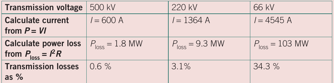
These calculations demonstrate that:
- 500 kV transmission is most economical (around 0.6% losses)
- transmission has acceptable losses (2-3%)
- transmission has unacceptably high losses (34.3%)
Reducing resistance in transmission lines
Besides using high voltages, power companies can reduce transmission losses by minimising the resistance of transmission lines. The resistance of wires depends on:
where:
- = resistance ()
- = resistivity ()
- = length (m)
- = cross-sectional area (m²)
Three approaches to reducing resistance
1. Reduce the length of wire ()
This is usually not practical. Power stations must be located near their fuel or energy sources:
- Thermal power stations need access to coal, gas or nuclear fuel
- Hydroelectric stations need water sources
- These are typically far from cities
Additionally, most people don't want pollution or potential dangers from power stations near residential areas.
2. Reduce the resistivity () by using better conductors
Gold, silver and copper are excellent conductors (resistivities around to ). However:
- Gold and silver are prohibitively expensive for bulk use
- Copper is expensive and heavy
Solution: Aluminium Conductors
Most countries use aluminium as the conductor. Although aluminium has higher resistivity than copper, it is:
- Much cheaper than gold, silver or copper
- Considerably lighter (reducing costs for support structures)
To increase strength, aluminium strands are wound around a core of galvanised steel wires.
3. Increase the cross-sectional area ()
Doubling the radius gives four times the cross-sectional area and one-quarter of the resistance. However:
- This also increases mass by a factor of four
- Eventually requires sturdier, uneconomic support structures
This method is only practical until the extra mass becomes too costly.
Disadvantages of very high voltage transmission
You might wonder why we don't use even higher voltages than to reduce losses further. The answer involves several practical limitations:
Corona phenomena
The Corona Effect: A Critical Limitation
Extra high voltage (EHV) can cause the air surrounding conductors to break down—called the corona effect:
- Air molecules break down when voltage gradient reaches
- lines need at least 600-700 mm clearance from pylons to avoid sparking
- A line would throw lethal arcs to the ground almost continuously
Additional problems from corona discharge
The air leakage from lines creates:
- Additional power losses
- TV, mobile phone and radio interference
- Visual coronas (eerie glowing around wires at night)
- Audible crackling effects (more prevalent in humid climates)
You may have heard your local power pole transformer crackle during wet winter months. This same effect limits transmission voltages.
Practical voltage limits in Australia
In Australia, 500 kV appears to be the current practical limit for electrical power transmission. For shorter distances (called sub-transmission areas), lower voltages are acceptable, safer and more economical:
This is because resistance is lower over shorter distances (smaller in the formula ).
Overall system losses: In Australia, it is estimated that the overall rate of power loss for the whole transmission system amounts to about 10% of generation—a substantial amount of energy.
Exam skills: solving transmission problems
A typical exam problem involves analysing a power supply system with transformers and calculating power losses. Follow these steps:
Key Steps for Success
-
Read the diagram carefully: Note which direction power flows. Don't assume the power station is always on the left!
-
Identify transformer types:
- Step-up: Secondary voltage > Primary voltage
- Step-down: Secondary voltage < Primary voltage
-
Use the correct formulas:
- Turns ratio:
- Power:
- Ohm's law:
-
Calculate systematically:
- Find currents using
- Calculate power loss using
- Find voltage drops using
- Add voltage drops to find total required voltage
-
Show your working: Exam markers award marks for method, not just the final answer.
Why high voltage is better than low voltage
When explaining why transmission uses high voltages (e.g., rather than ):
- Mention power loss formula:
- Explain that transmitted power is fixed:
- Show that higher voltage means lower current
- Demonstrate with numerical comparison: currents are in ratio when voltages are in ratio
- Show power losses are in ratio or approximately
Remember!
Key Points to Remember:
-
Transmission losses are minimised by using high voltages, which reduce current and therefore reduce losses in the wires.
-
For every factor of 10 increase in voltage, current decreases by a factor of 10, and power loss decreases by a factor of 100.
-
Step-up transformers increase voltage (and decrease current) for transmission; step-down transformers decrease voltage (and increase current) for safe use by consumers.
-
Power loss formula: shows that reducing current is the most effective way to reduce transmission losses.
-
Australia typically uses 500 kV for long-distance transmission, which gives acceptably low losses (around 0.6%). Higher voltages are impractical due to corona discharge effects.
-
Aluminium conductors are used for transmission lines because they offer a good balance of low cost, low weight and reasonable conductivity.