Transformers: Electromagnetic Induction at Work (VCE SSCE Physics): Revision Notes
Transformers: Electromagnetic Induction at Work
Introduction
Transformers are devices that use electromagnetic induction to change the voltage of an alternating current. They are essential components in electrical power distribution, allowing electricity to be transmitted efficiently over long distances and then stepped down to safe voltages for use in homes and businesses.
Before exploring how transformers work, let's consider a practical application of electromagnetic induction: regenerative braking in electric vehicles. When you brake in an electric or hybrid car, the electric motor reverses its function and becomes a generator. Instead of converting electrical energy into motion, it converts the vehicle's kinetic energy back into electrical energy, which recharges the battery. This process recovers energy that would otherwise be lost as heat in traditional friction brakes. Some drivers report recapturing between 15-20% of their total energy use during normal trips, and up to 32% when driving on hilly terrain. This demonstrates the practical importance of electromagnetic induction in everyday technology.
What is electromagnetic induction?
Electromagnetic induction is the process of generating an electric current with a changing magnetic field near a wire, or by moving a metal wire in a steady magnetic field.
You learned in earlier studies that electricity can be generated by moving permanent magnets or electromagnets inside coils of wire, or by rotating coils of wire inside magnetic fields. This follows Faraday's law of electromagnetic induction:
where is the induced emf (in volts), is the number of turns in the coil, is the change in magnetic flux (in weber), and is the time interval (in seconds).
In generators, the magnetic flux changes due to physical movement of the coil relative to the magnetic field. However, it is also possible to induce an emf with no moving parts at all. From Faraday's law, all that is needed is to create a changing magnetic flux.
The key requirement for electromagnetic induction is a changing magnetic field or flux. A constant magnetic field will not induce an emf, which is why transformers require alternating current to function.
How transformers work
Consider two coils placed side by side, as shown in the diagram below. One coil is called the primary coil and the other is the secondary coil.
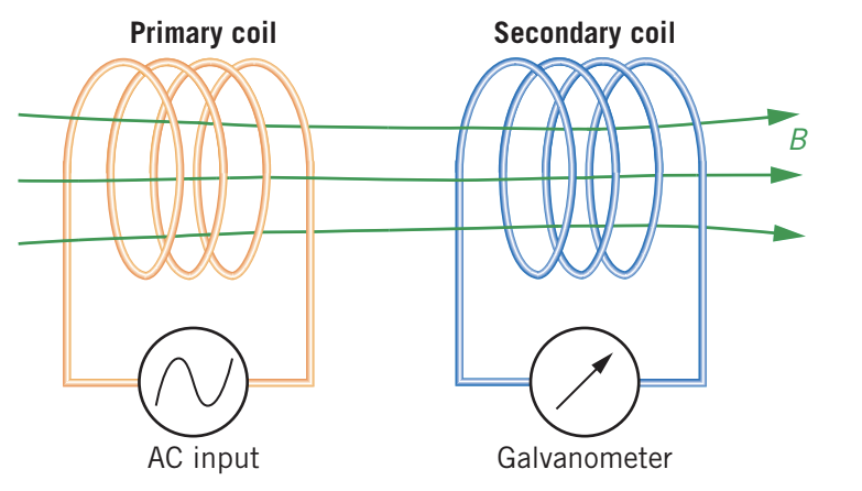
When an alternating current (AC) passes through the primary coil, it produces a changing magnetic field. This changing magnetic field creates a changing magnetic flux that passes through the secondary coil. According to Faraday's law, this changing flux induces an emf in the secondary coil, even though there are no moving parts.
The key point is that a transformer requires a changing current in the primary coil. If you connected a steady direct current (DC) to the primary coil, the magnetic flux would be constant and no emf would be induced in the secondary coil. This is why transformers only work with alternating current.
A transformer is a device that changes voltage through electromagnetic induction in an alternating current.
Structure of a transformer
The efficiency of a transformer is greatly improved by winding both coils onto a soft iron core. The soft iron increases the overall magnetic flux linking the coils. When the primary and secondary coils are wound onto opposite sides of a continuous soft iron core, as shown below, the magnetic flux between them is even stronger.
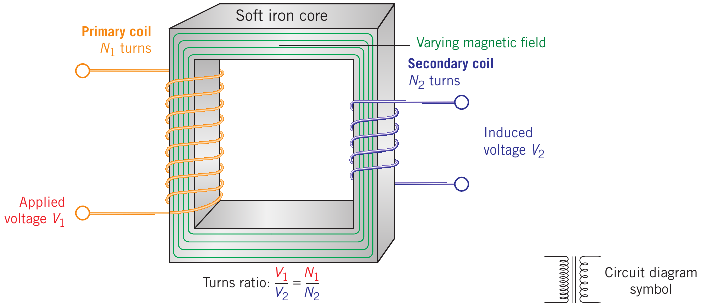
The diagram shows the key components:
- Primary coil with turns, connected to an applied voltage
- Secondary coil with turns, producing an induced voltage
- Soft iron core that carries the magnetic flux between the coils
- The circuit symbol for a transformer (shown at bottom right)
The term "soft iron" refers to iron that has been heat-treated to make it more ductile and has not had carbon added (as in steel-making). Soft iron has desirable magnetic properties for transformers: it is easily magnetised and demagnetised, and it is highly permeable to magnetic flux. This means it is very effective at carrying the magnetic field between the coils.
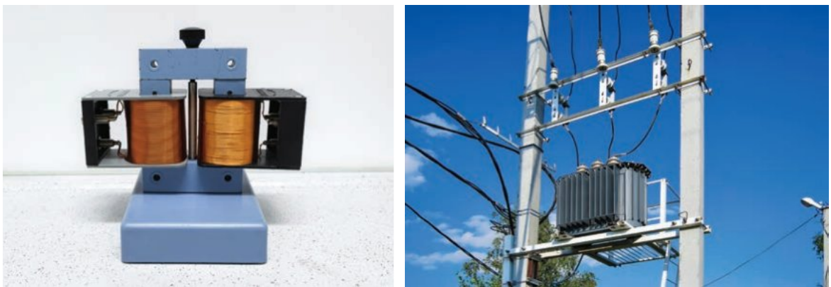
Real transformers come in many sizes, from small phone chargers to large industrial units mounted on power poles:
The turns ratio
The relationship between the voltages in the primary and secondary coils depends on the number of turns in each coil. This relationship is given by the turns ratio:
where:
- = primary voltage (V)
- = secondary voltage (V)
- = number of turns per unit length on the primary coil
- = number of turns per unit length on the secondary coil
By changing the turns ratio (the number of turns on either the primary or secondary coil), you can make the secondary voltage greater or smaller than the primary voltage.
Step-up and step-down transformers
A step-up transformer is one where the secondary voltage is greater than the primary voltage. This occurs when (more turns on the secondary coil).
A step-down transformer is one where the secondary voltage is smaller than the primary voltage. This occurs when (fewer turns on the secondary coil).
It is the ratio, not the actual number, of turns in each coil that matters. For example, a transformer with 2000 turns on the primary and 50 turns on the secondary has the same turns ratio as one with 200 turns on the primary and 5 turns on the secondary.
You may have seen step-down transformers mounted high up on power poles in your street. These step down the high transmission voltage to 230 V for safe use in homes.
Worked example: calculating secondary voltage
Worked Example: Calculating Secondary Voltage
Question: The ratio of number of turns in an ideal step-up transformer is . An alternating rms voltage of 12 V is supplied to the primary coil. Calculate the rms secondary voltage.
Solution:
We need to find , so we rearrange the turns ratio formula:
Given V and (inverting the ratio given in the question), we substitute:
Ideal transformers and power conservation
In an ideal transformer, no electrical energy is transformed to thermal energy. This means that the power input to the primary coil equals the power output from the secondary coil:
Since power equals voltage multiplied by current (), we can write:
where and represent the primary and secondary currents respectively.
Combining this with the turns ratio gives us the complete formula for an ideal transformer:
This reveals an important principle: if the voltage is stepped up, the current is stepped down, and vice versa. This makes sense because power must be conserved. If a transformer increases the voltage by a factor of 10, it must decrease the current by the same factor of 10 to keep the power constant.
Real transformers and efficiency
In reality, the output power from the secondary coil can never be greater than the input power because energy must be conserved. Real transformers are not perfectly efficient. High-quality transformers typically have efficiencies of 98-99%, with the remaining 1-2% being transformed to waste thermal energy.
You may have felt this waste heat when using small transformers at home to charge your phone or laptop. On large transformers used by power utilities, the excess heat is removed by circulating oil (convection) or using air-cooled radiators with fins. You may also notice a humming noise from transformers, as some electrical energy is transformed into sound energy.
Study skills: annotating and drawing diagrams
When solving transformer problems, it is helpful to draw and annotate a diagram. This ensures you understand the situation and don't miss any vital information.
Follow these steps:
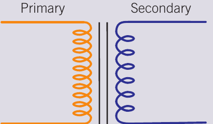
Step 1: Draw a simple transformer diagram showing the primary and secondary coils.
Step 2: Read through the question carefully and highlight or annotate each piece of information, labelling it with the appropriate symbol (, , , , , ).
Step 3: Add the values to your diagram, placing them on the correct side (primary or secondary).
Step 4: Identify which formula you need based on what you know and what you need to find.
Step 5: Substitute the values into the formula and solve.
Example problem
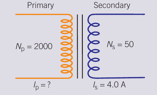
Worked Example: Finding Primary Current
Question: A phone charger with 2000 turns in the primary coil and 50 turns in its secondary coil draws a current of 4.0 A. Calculate the current in the primary coil.
Solution:
After drawing and annotating a diagram (as shown above), we identify that we need to find (primary current) and we know A, , and .
Using the current relationship for an ideal transformer:
Substituting the values:
Tip for remembering the formula: Transformers are named step-up or step-down according to what they do to the voltage, so must match in the formula (either both on top or both on bottom of the fraction). For current, it's the opposite: when voltage steps up, current steps down, which is why appears with in the formula.
Remember!
Key Points to Remember:
-
Electromagnetic induction generates an emf through a changing magnetic field near a wire. Transformers use this principle with no moving parts.
-
Transformers only work with AC, not DC. The alternating current creates a continuously changing magnetic flux, which induces an emf in the secondary coil.
-
The turns ratio determines voltage transformation: . More turns on the secondary coil creates a step-up transformer; fewer turns creates a step-down transformer.
-
For ideal transformers, power is conserved: , which means . When voltage steps up, current steps down proportionally.
-
Real transformers have efficiencies of 98-99%, with small amounts of energy lost as heat and sound. The soft iron core improves efficiency by effectively carrying the magnetic flux between coils.