Coding Systems (AQA A-Level Computer Science): Revision Notes
Coding Systems
Introduction to character encoding
Binary sequences serve a dual purpose in computer systems. While we've explored how binary represents numerical values for calculations, it also encodes text and characters for communication and display. Every character you type on a keyboard has a corresponding character code, which is its binary representation stored and processed by the computer.
An important distinction exists between using binary for numerical calculations versus character representation. When you enter a house number or telephone number, the digits are stored using their character codes rather than as pure numbers, since you won't be performing mathematical operations on them. Different encoding systems handle this character representation.
ASCII and Unicode
The early days of character encoding
In computing's early history, programmers developed their own systems for representing characters using binary sequences. For instance, one programmer might decide that 00000000 represented the letter A whilst 00000001 represented B. The problem was obvious: different programmers used different coding schemes, meaning the same binary sequence could represent entirely different characters depending on who created the system.
ASCII: establishing a standard
To resolve this confusion, a universal standard emerged called ASCII (American Standard Code for Information Interchange). This 7-bit encoding system provides 128 unique combinations (), sufficient for representing:
- All keyboard characters (uppercase and lowercase letters)
- Numbers on the keypad
- Special characters (%, @, /, #, etc.)
- Non-printing control characters (ACK, BS, etc.) used for device communication
Extended ASCII later expanded this to an 8-bit code, allowing for 256 different characters.
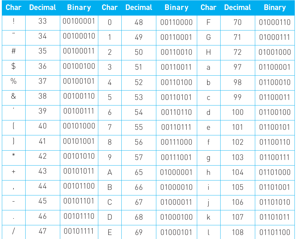
The table above shows an extract of the ASCII character set. You don't need to memorise these codes, but understanding the principle behind them is essential.
Limitations of ASCII
Despite its widespread adoption, ASCII has several limitations:
Key limitations of ASCII:
- The 256-character limit cannot represent all possible characters, numbers and symbols globally
- Initially developed in English, it fails to represent characters from other languages and scripts adequately
- The explosion of web usage made having a universal international coding system crucial
- The proliferation of different platforms and programs demanded a much wider character range
Unicode: the modern standard
Unicode emerged as a more comprehensive standard that incorporates ASCII's basic principles whilst extending far beyond it. In one of its forms, Unicode assigns a unique 8-bit code to every keyboard character on a standard English keyboard. Crucially, ASCII codes have been integrated within Unicode, so the ASCII code for capital letter A (65) remains the Unicode code for that same character.
Unicode's true power lies in its international character support, covering over 20 countries and even including conversions for classical and ancient characters. To accommodate these additional characters, more than 8 bits per character are required. Two common Unicode encodings exist today:
- UTF-8: Uses varying bit lengths
- UTF-16: Uses a fixed 16-bit code
Unicode continues to evolve, constantly updated to include more of the diverse languages of our modern world. Languages such as Arabic and Chinese use significantly different alphabets to English, and even similar languages like French and German contain specific characters not found on standard English keyboards.
The critical importance of universal standards cannot be overstated. With data constantly being transmitted across global networks, inconsistent encoding systems would cause data corruption when used on systems other than the one on which it was created. Unicode aims to provide complete coverage across every platform in terms of hardware and operating systems, every foreign language, and every program.
Parity: a simple error detection method
Parity is a straightforward method of checking binary codes by counting the number of 0s and 1s in the code. The technique works by examining whether the number of ones in a binary sequence is even or odd.
Data transmission is constant in computer systems, with all this data composed of binary sequences. During processing or transmission, data can become corrupted. A parity bit is added to binary data to help detect these errors during transmission.
When sending data as a series of 0s and 1s, slight variations in carrier wave frequency might cause a 0 to be misinterpreted as a 1, making the data unreliable. Consider the Unicode character transmitted as binary code 01101111. This code could become corrupted as it passes through a computer system or across a network.
The parity bit system works as follows:
Even parity
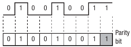
The number of 1s in the code are counted. If there's an odd number of 1s, the parity bit is set to 1 to make the total number of 1s even. Upon reception, the data is checked to ensure an even number of 1s remains. If this condition is met, the data is assumed correct.
In the top example from the diagram, the parity bit is set to 0 to maintain an even number of ones.
Odd parity
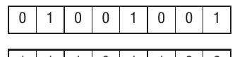
The number of 1s in the code are counted. If there's an even number of 1s, the parity bit is set to 1 to make the total number of 1s odd. Upon reception, the data is checked to ensure an odd number of 1s remains. If this condition is met, the data is assumed correct.
The bottom example shows the parity bit set to 1 to ensure an even number of ones.
Important limitation: Parity checking is quite simple and won't identify all errors in transmission. It can only detect that an error has occurred, not correct it.
Majority voting
Majority voting offers another error detection approach by transmitting the same data multiple times and comparing the results. For the binary code 1001, the data would be sent three times as:
111000000000111
How Majority Voting Works:
When checking received data, you'd expect patterns of three identical bits. The first bit shows 111, then 000, and so on. Where discrepancies exist, majority voting determines which bit occurs most frequently. For example, if the same code 1001 was received as:
101010000111
You could deduce that the first bit should be 1 (two out of three bits are 1), the second bit is 0 (two of three bits are 0), and so forth for the remaining bits.
This principle scales up for critical applications. On Space Shuttle missions, for instance, the Columbia had at least four computers processing identical data and comparing results. Where discrepancies arose between results, majority voting identified the correct course of action.
Check digits
Check digits provide a common method for verifying data accuracy, particularly when data is entered into computers. For example, barcodes printed on supermarket goods use check digits. Like parity bits, a check digit is a value added to the end of a number to verify the number hasn't been corrupted.
The check digit is created by manipulating the digits that make up the number itself, using them to generate a single digit. The simplest but most error-prone method involves adding all the digits together, then continuing to add the resulting digits until only a single digit remains.
For instance, the digits of 123456 add up to 21, and 2 and 1 add up to 3, so the number with its check digit becomes 1234563. During data processing, the check digit is recalculated and compared with the transmitted digit. Matching digits suggest the data is correct; a discrepancy triggers an error message.
However, this system has a weakness: if two numbers are transposed (swapped), the check digit will be identical. For example, both 1234 and 4321 add up to 10, producing a check digit of 1.
Modulo-11 check digit calculation
To overcome this limitation, each number in the pattern receives a weighting (multiplied by a different weight or scaling factor). A common calculation method known as modulo-11 works as follows:
Worked Example: Modulo-11 Check Digit Calculation
- Original number: 1, 2, 3, 0, 4, 5
- Weighting (starts from 2, not 1): 6, 5, 4, 3, 2
- Multiply by weight: 12, 15, 0, 12, 10 = 49
- Add together: 12 + 15 + 0 + 12 + 10 = 49
- Divide by 11: 49 ÷ 11 = 4 remainder 5
- Subtract remainder from 11: 11 - 5 = 6
- So the check digit is 6, making the number
230456
This weighted approach ensures that transposed numbers will produce different check digits, significantly improving error detection.
Bit-mapped graphics
Binary representation extends beyond text and numbers to include graphics. Graphics on your computer display can range from simple line drawings to full animations. All computer graphics are represented using sequences of binary digits (bits).
Understanding pixels and resolution
Monitor displays comprise thousands of tiny dots or picture elements called pixels. A typical monitor might have a grid of 1366 by 768 pixels, known as the resolution. This term applies both to screens and individual image files. The formula for resolution in pixels is:
You can also define resolution in terms of pixels per inch (PPI). For example, a monitor measuring 12 × 9 inches with 1366 by 768 pixels will have approximately 114 PPI horizontally (1366 ÷ 12) and around 85 PPI vertically (768 ÷ 9).
How bit-mapping works
Each pixel can be controlled to display different colours. By combining pixels, images are created on screen. At the simplest level, each pixel could be controlled by one bit, mapped to one bit in memory. The bit could be set to either 0 or 1, representing off or on - in this case, black or white.
The diagram shows how binary data stored in memory translates to a displayed pattern on screen, with 1s appearing as filled (grey) squares and 0s as empty (white) squares.
Colour depth
To create colour graphics, each pixel is mapped to more than one bit. For example, a pixel might be represented by a byte (8 bits) in memory. This means each pixel could be any one of or 256 different colours. The amount of memory allocated to each pixel is called the colour depth.
The amount of memory allocated for bit-mapping depends on the graphics card's memory capacity:
Worked Example: Calculating Image Memory Requirements
If 24 bits were allocated to each pixel, this would give combinations or 16,777,216 different colours. Twenty-four bits are typically used as eight bits are allocated to each of the three primary colours: red, green and blue (RGB), from which all other colours are created.
For a 1024 × 768 display with 24 bits per pixel, you get 18,874,368 bits or 2.35 MB of memory to make one picture:
- Screen resolution of 1024 × 768 = 786,432 pixels
- 24 bits allocated to each pixel = 786,432 × 24 = 18,874,368 bits
- Divide by 8 to get bytes = 2,359,296 bytes
- Convert to megabytes = 2.36 MB
Metadata in Bitmaps: Bitmaps may also contain metadata in a header at the beginning of the file, storing information about the file itself, such as file type, width and height in pixels, and colour depth.
Vector graphics (A level only)
Vector graphics are created using objects and coordinates rather than pixels. A vector is a measure of quantity and direction. It's easier to think of vector graphics as geometric shapes.
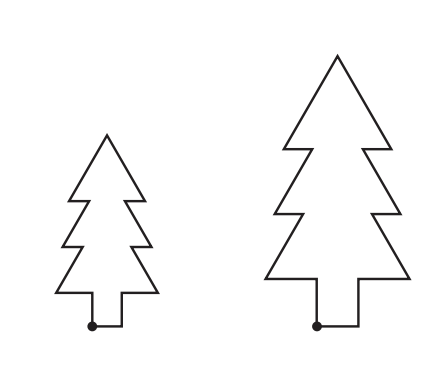
For example, if we had a vector graphic of a square, it would comprise four coordinates with lines drawn between them. To rescale the object, we simply adjust the coordinates. Therefore, the graphics are controlled mathematically rather than being completely regenerated as with a bit map.
The diagram shows two versions of a simple tree shape at different scales - both created from the same coordinate information.
Advantages of vector graphics
Vector graphics offer several benefits over bit-mapped images:
- File size: Vector graphic files are much smaller than bit-mapped files because they contain the mathematical description required to create an image rather than storing the actual image pixel data
- Scalability: When drawn at different scales, images are rendered using the mathematical description, making them perfect for scenarios requiring rescaling
- Versatility: Not practical for every scenario where graphics are needed, such as scanning and digital photography
Components and applications
An image created on screen comprises lines, with the scale and position of these lines adjusted as the screen display changes to create the image.
Vector images are made up of primitives - the basic pieces of data needed to create an image. Typically, these include points, lines, curves and polygons. Common shapes are included, as well as letters. Colour gradients may also be contained as primitives.
CAD/CAM packages make extensive use of vector graphics as these packages rely on line-based drawings. Some two- and three-dimensional animation programs also use vector graphics. Since an animated image is a series of still images combined together, once the still image has been created, the vectors can be manipulated to create the various frames within the animation.
Analogue and digital signals
All processing carried out by computers is digital, yet there are occasions when either the input or output required is analogue. For example, some data sent around the Internet travels in analogue form over telephone networks. This is because telephone lines were originally designed to carry voice data, which is analogue. A microphone takes speech input (analogue), or a musical instrument digital interface (MIDI) takes in data from a musical instrument which may be analogue.
Understanding analogue data
Analogue data are infinitely variable and are often represented in the form of a wave.
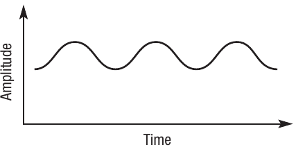
The diagram shows a typical sound wave - a smooth, continuously varying curve plotted against time and amplitude.
Understanding digital data
Digital data are represented as discrete values shown with the highs and lows as set peaks and troughs. As we've seen in this section, digital data are often represented as sequences of 0s and 1s.
The diagram shows a digital signal with distinct on/off states, contrasting with the smooth analogue wave.
Analogue to digital conversions
The challenge arises when we need to input analogue data into the computer or output digital data from the computer in analogue form. To achieve this, a converter is needed - either an analogue to digital converter (ADC) or a digital to analogue convertor (DAC).
Examples of ADC usage
One example where an ADC is used is between a microphone and a computer. The microphone inputs sound as changes in air pressure, then converts them into electrical signals. These analogue electrical signals are then converted by the ADC into digital signals that the computer can process.
Another example is a MIDI device for an acoustic guitar. This device fits beneath the strings on the guitar. When strings are played, they generate an analogue sound wave. The sound waves are picked up and converted to digital form.
MIDI event messages
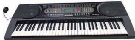
MIDI uses event messages to control various properties of the sound. These messages are typically encoded in binary and provide communication between MIDI devices or between a MIDI device and the processor. For example, on a MIDI keyboard, an event message may contain data on:
- When to play a note
- When to stop playing the note
- Timing a note to play with other notes or sounds
- Timing a note to play with other MIDI-enabled devices
- What pitch a note is
- How loud to play it
- What effect to use when playing it
Advantages of MIDI files
MIDI files offer several benefits over other digital audio formats:
- Size and speed: MIDI files tend to be much smaller, requiring less memory and loading faster - particularly advantageous when embedded in web pages
- Editability: MIDI files are completely editable as individual instruments can be selected and modified
- Choice: MIDI supports a very wide range of instruments, providing more choices for music production
- Quality: MIDI files can produce very high quality and authentic reproduction of the instrument
Sound sampling and synthesis
The sampling process
Sampling is the process of converting analogue sound waves into digital form to create what is commonly known as digitised or digital sound. This is sometimes referred to as analogue to digital (ADC) conversion.
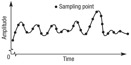
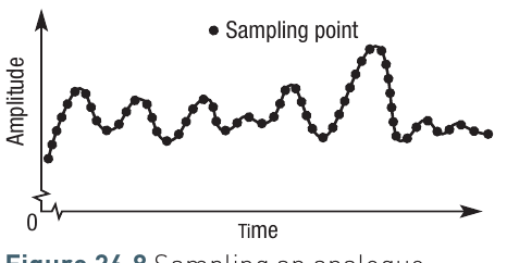
An analogue sound wave is infinitely variable, so to store this digitally, a series of readings at fixed intervals are taken from the wave. These readings create the discrete data values that form binary data, stored as binary codes. It's called sampling because you don't record every single change in amplitude of the waveform. Instead, you choose set points at which a reading (or sample) will be taken.
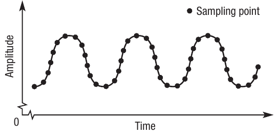
The diagram shows an analogue wave with discrete sampling points marked along it, illustrating where amplitude readings are taken.
The amplitude of the wave is only recorded at the point where each sample is taken. Other variations in amplitude are not recorded. Therefore, to create an exact replica of the analogue sound would require a sample to be taken every time the amplitude of the wave changed even by a small amount. However, the human ear doesn't notice very small changes, so sound can be faithfully created with fewer samples.
Calculating file size
The file size calculation uses this formula:
- Sample rate: The number of samples taken per second
- Length: The recording duration in seconds
- Sampling resolution: The number of bits allocated to representing the sound
Worked Example: Calculating Sound File Size
For example, three samples recorded at a resolution of 16 bits (two bytes) might look like:
0011110000000011
1111010101100101
0110011000111110
Assuming a sample rate of 44,000 Hz with a 60-second recording, the file size would be:
Nyquist's Theorem
When deciding on the optimum sampling rate, many programmers refer to Nyquist's Theorem. This states that to faithfully recreate the analogue signal, you should sample at least twice the highest frequency.
Nyquist's Theorem in Practice:
For example, if the human ear can cope with frequencies of 20 Hz – 20,000 Hz, then the analogue frequency must be sampled at at least 40,000 Hz. The reason for doubling the frequency is to ensure that the sample covers the complete range of peaks and troughs in the analogue signal, which then allows a faithful reproduction of the sound.
Editing and synthesis
Samples can be edited to remove any background noise or interference from the original sound wave. Some people argue that CDs produce better quality sound than vinyl disks for this reason.
Sound synthesis is another term that refers to sound produced digitally rather than in analogue format. It means that the sound is synthesised or manufactured rather than being in its original analogue format. By definition, all sounds created by a computer are digital.
Digital to analogue conversion
After sound has been digitally recorded, to hear it, the user will use either earphones or speakers. These devices are driven by audio signals yet the data is stored as digital signals. To convert it so that it can be amplified and played, a digital to analogue convertor (DAC) is required.
Typically, the DAC is embedded in the device that plays the audio data and the signal is passed in analogue form to the loudspeakers or headphones.
Data compression
There are many scenarios where files used to store data can become very large. For example, high resolution photographs or music sampled at a high frequency will result in files that could be several megabytes. A whole movie will take up several gigabytes. To reduce storage requirements and make it quicker to transmit these files, they are often compressed.
Understanding compression
Compression is the process of encoding information with fewer bits, so that the files take up less memory. There are several methods for doing it, depending on the type of data being encoded. You're probably familiar with the concept of using zip files, or reducing a high resolution image to low resolution. Many familiar file types such as jpeg, mpeg and mp3 are compressed files.
Any type of data can be compressed and different techniques are used depending on the data type. These techniques lead to either lossless or lossy compression:
- Lossless: The compressed file is as accurate as it was before compression - no data is lost
- Lossy: There will be some degradation in the data, for example, a grainier image might be produced
Lossless compression
Run-length encoding
Imagine a picture made up of millions of pixels. The picture file will contain data about each pixel, for example its colour. Part of the file might simply read: blue, blue, blue, dozens of times where there is a run of blue pixels. Rather than storing the same data over and over, you can use run-length encoding, which states that the next x pixels will be blue.
Run-Length Encoding Example:
B,B,B,B,B,B,B,B becomes 8B.
This is a simple example but you can see that only two encoded digits are needed to represent eight uncompressed ones, with no loss of data accuracy.
Dictionary-based encoding
When compressing text files, dictionary-based compression techniques can be used. These work on the basis that within text, there will be common strings of characters. Rather than rewriting these same strings, they can be coded in some way.
For example, the characters 'tion' are commonly found at the end of many words, such as 'station', 'nation' and 'creation'. Rather than storing the words individually, 'tion' can be encoded to the dictionary and then used in combination with other prefixes to form words. At the same time, 'sta', 'na' and 'crea' can be encoded to the dictionary as they too can be made into other words.
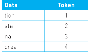
Now when you need to encode any words that contain those strings of text, you can use the dictionary entry rather than writing the whole strings out again in the file.
A data file containing the strings 21, 31, 41 would result in the words 'station', 'nation' and 'creation' but use six characters instead of 21 characters.
Dictionary-based techniques can be used on non-text data if it is considered as a sequence of 0s and 1s.
Lossy compression
There are cases where lossless compression still results in a large file as there is a limit to how small it can get whilst still maintaining accuracy. In some cases where the amount of memory is an issue, or where data is being transmitted across a network and the speed of transmission is vital, it might be necessary to make these files even smaller.
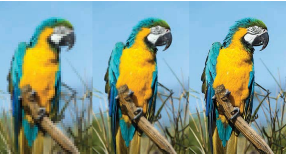
The image shows three versions of the same parrot at progressively lower resolutions, demonstrating the visual effect of lossy compression.
This is often the case with streaming audio or video. In these cases, a compression technique that leads to some degradation in data quality may be acceptable. For example, if you were streaming a movie, you might not expect the picture quality to be as good as that on a DVD.
Trade-offs in Compression:
Programmers must take into account issues such as memory and transmission requirements when deciding on the most appropriate compression techniques. The widespread use of mobile data on various portable devices means that lossy compression is commonly used, even though it leads to a degradation of the original data.
JPEG compression
Lossy compression techniques work by identifying data that can be removed whilst still creating an acceptable representation. In the case of audio, graphics and video, the user will have some control over the level of compression and therefore the quality of the compressed file. For example, a low resolution JPEG file will have more of the original data removed and therefore produce a pixellated image.
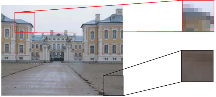
The diagram shows a palace building with detail boxes highlighting how JPEG compression affects different frequency areas of an image.
JPEG compression works by breaking an image up into blocks of 8 × 8 pixels. In each block, the data is converted into frequencies. Some frequencies are considered to be more important than others.
This is because high frequency data is more difficult for the human eye to perceive, so changes made to high frequency data will be less noticeable. Low frequency data on the other hand is more noticeable.
For example, in the illustrated building, the 8 × 8 pixel grid of a grey road is a high frequency image as the human eye will not notice slight changes in the grey. However, if you look at the red box that represents another 8 × 8 grid, there is a large contrast between the dark building and the light sky. When compressing the image it is important to maintain this contrast. The slight contrasts in grey on the road are much less important.
Therefore, JPEG analyses the pixel data within each 8 × 8 block and removes data that is least likely to affect the human perception of the image. It then uses the same run-time encoding methods described above to eliminate any repeating data to reduce the file size.
Key Points to Remember:
-
Character codes translate keyboard characters into binary - ASCII and Unicode are the two main standards, with Unicode being more comprehensive and supporting international characters
-
Error checking methods like parity bits, majority voting, and check digits help detect (and sometimes correct) data corruption during transmission or processing
-
Bit-mapped graphics are made up of individual pixels, with resolution (width × height) and colour depth determining the file size and image quality
-
Vector graphics use mathematical descriptions of objects and coordinates, allowing perfect scaling and smaller file sizes for certain applications (A-level only)
-
Analogue signals are continuous and infinitely variable (like sound waves), whilst digital signals are discrete values (0s and 1s) - ADC and DAC converters translate between these formats
-
Sound sampling converts analogue audio to digital by taking readings at fixed intervals - Nyquist's Theorem suggests sampling at twice the highest frequency for faithful reproduction
-
Compression reduces file sizes through either lossless methods (like run-length encoding and dictionary-based encoding) that maintain perfect accuracy, or lossy methods (like JPEG) that sacrifice some quality for greater size reduction